
Structural Design with RCC Elements
Introduction
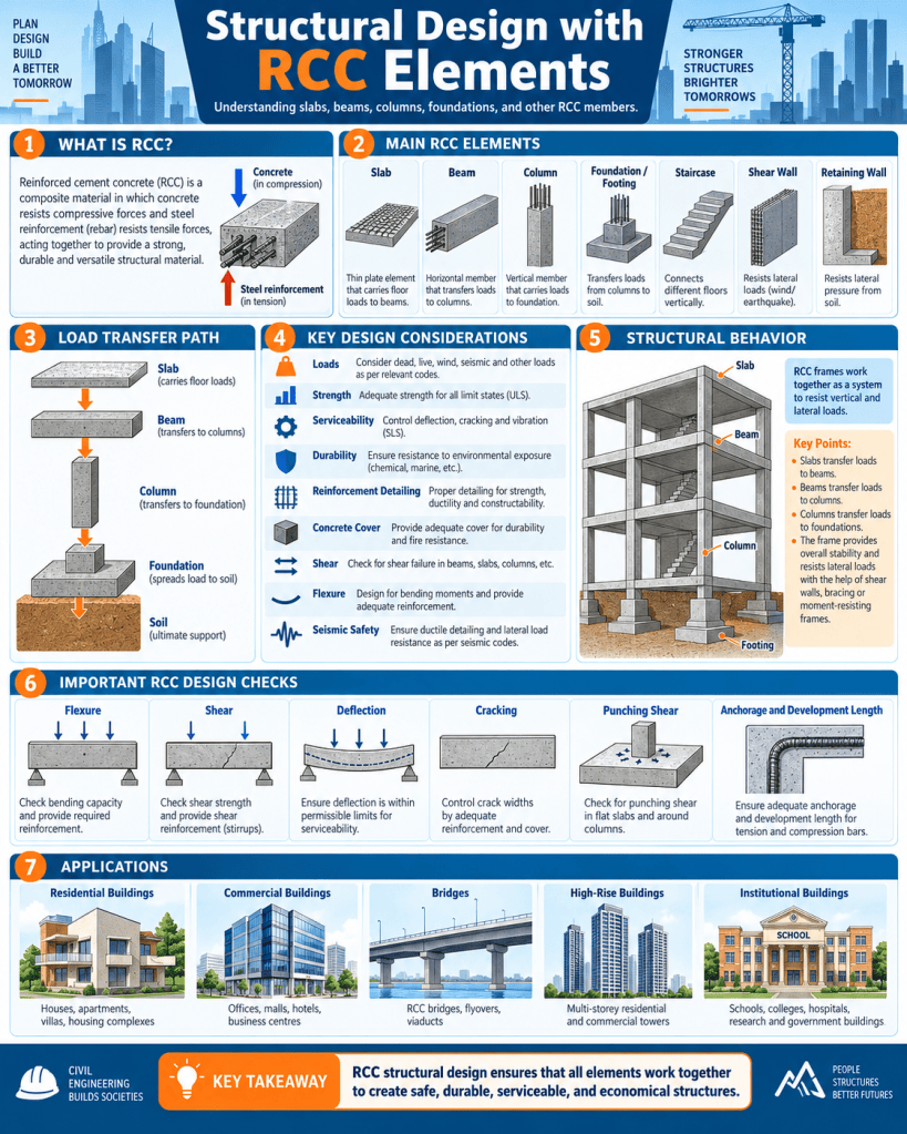
Reinforced Cement Concrete (RCC) is one of the most widely used structural systems in buildings and infrastructure. It combines the compressive strength of concrete with the tensile strength of steel reinforcement, allowing structural members to resist different types of loads safely and efficiently. RCC is extensively used in residential buildings, commercial complexes, bridges, industrial structures, institutional buildings, retaining walls, water tanks, and high-rise construction.
Structural design with RCC elements involves determining suitable sizes, reinforcement, detailing, and arrangement of members so that the structure remains safe, serviceable, durable, and economical throughout its intended life. The main RCC elements include slabs, beams, columns, foundations, staircases, shear walls, and retaining walls. These components work together to transfer loads from the building to the ground.
Basic Principle of RCC
Concrete performs very well in compression but has relatively low tensile strength. Steel, on the other hand, has excellent tensile capacity. In RCC, steel reinforcement is placed in regions where tension is expected.
The bond between concrete and steel allows them to act together as a composite structural material.
The basic load path in a framed building is generally:
Slab → Beam → Column → Foundation → Soil
Each structural component must therefore be designed not only individually but also as part of an integrated load-transfer system.
Objectives of RCC Structural Design
The main objectives of RCC design are to ensure:
- structural safety;
- adequate strength;
- stability;
- serviceability;
- durability;
- fire resistance;
- economy;
- constructability.
A structure should not collapse under design loads, but it should also not experience excessive cracking, vibration, or deflection during normal use.
Loads Considered in RCC Design
Structural design begins with identifying the loads acting on the building.
Dead Load
Dead load includes the permanent weight of:
- RCC members;
- walls;
- floor finishes;
- roofing;
- fixed equipment.
Live Load
Live load includes temporary or movable loads caused by:
- occupants;
- furniture;
- storage;
- movable equipment.
Wind Load
Wind produces lateral pressure and suction on buildings.
It becomes particularly important for tall buildings, large roofs, and exposed structures.
Earthquake Load
Earthquake forces result from ground motion and structural inertia.
Seismic design is especially important in earthquake-prone regions.
Other Loads
Depending on the structure, designers may also consider:
- snow loads;
- soil pressure;
- water pressure;
- temperature effects;
- impact;
- equipment vibration.
Limit State Design of RCC
Modern RCC structures are commonly designed using the Limit State Method.
Two broad categories are checked:
Ultimate Limit State
This concerns safety against failure due to:
- bending;
- shear;
- compression;
- torsion;
- instability;
- collapse.
Serviceability Limit State
This concerns satisfactory performance under normal use.
Typical checks include:
- deflection;
- cracking;
- vibration;
- durability.
The structure must satisfy both.
RCC Slabs
A slab is a horizontal structural element used to form floors and roofs.
Slabs transfer loads to beams, walls, or directly to columns.
Common slab types include:
- one-way slabs;
- two-way slabs;
- flat slabs;
- cantilever slabs.
One-Way Slab
A one-way slab primarily bends and transfers load in one direction.
This usually occurs when the slab is supported on two opposite sides or when the longer span is significantly greater than the shorter span.
Main reinforcement is generally placed along the shorter span.
Distribution reinforcement is provided perpendicular to it.
Two-Way Slab
A two-way slab transfers load in both directions.
It is commonly used when the slab is supported on all four sides and the plan dimensions are relatively comparable.
Reinforcement is provided in both directions.
Two-way action can reduce bending moments compared with one-way action.
Flat Slab
A flat slab is supported directly by columns without conventional beams.
Its advantages include:
- reduced structural depth;
- flexible floor planning;
- simpler service routing;
- clean ceiling appearance.
However, punching shear around columns becomes an important design concern.
Drop panels or column heads may be used where necessary.
Cantilever Slab
A cantilever slab is fixed at one end and free at the other.
Typical applications include:
- balconies;
- sunshades;
- canopies.
The main tensile reinforcement is generally placed near the top surface close to the support.
RCC Beams
Beams transfer loads from slabs and walls to columns or other supports.
They primarily resist:
- bending moments;
- shear forces;
- sometimes torsion.
In a simply supported beam under downward gravity loading, the bottom region is generally in tension and the top region in compression.
Beam Reinforcement
Typical beam reinforcement includes:
Main Bars
These resist flexural tension.
Stirrups
Stirrups provide shear resistance and hold longitudinal reinforcement in position.
Top Bars
Top reinforcement is particularly important at supports in continuous beams and cantilevers.
Bottom Bars
Bottom reinforcement is commonly required at midspan in simply supported beams.
Proper anchorage and development length are essential.
Simply Supported Beams
A simply supported beam rests on supports at both ends.
The maximum positive bending moment generally occurs near midspan.
These beams are conceptually simple but are less common in monolithic RCC frames where continuity is usually present.
Continuous Beams
Continuous beams extend over more than two supports.
They develop:
- positive moments in spans;
- negative moments over supports.
Reinforcement must therefore be arranged appropriately in both top and bottom zones.
Cantilever Beams
Cantilever beams are fixed at one end and free at the other.
The top surface near the fixed support is usually in tension under downward load.
Cantilevers are used for balconies, canopies, projections, and architectural features.
RCC Columns
Columns are vertical structural members that transfer loads from beams and slabs to foundations.
They are mainly subjected to compression but may also experience bending moments.
Columns may be:
- square;
- rectangular;
- circular;
- L-shaped;
- T-shaped.
Their design depends on:
- axial load;
- bending moment;
- slenderness;
- reinforcement ratio;
- support conditions.
Short and Slender Columns
A short column is less sensitive to buckling and generally fails by compression or material strength.
A slender column can experience significant additional bending due to lateral deflection.
Slenderness must therefore be checked carefully.
Column Reinforcement
Column reinforcement includes:
Longitudinal Bars
These carry axial and bending forces.
Lateral Ties
These hold the longitudinal reinforcement in position and provide confinement.
Spiral Reinforcement
Circular columns may use helical reinforcement.
Good confinement improves ductility, particularly under seismic loading.
Beam-Column Joints
Beam-column joints are critical areas in RCC frames.
They transfer forces between horizontal and vertical structural elements.
Under earthquake loading, these joints may experience high shear stresses and repeated load reversals.
Good detailing includes:
- proper anchorage;
- adequate confinement;
- closely spaced ties;
- correct bar continuity.
Poor joint detailing can lead to brittle failure.
RCC Foundations
Foundations transfer column and wall loads safely to the soil.
Common RCC foundations include:
- isolated footings;
- combined footings;
- strap footings;
- raft foundations;
- pile caps.
Foundation design depends heavily on soil bearing capacity and settlement.
Isolated Footing
An isolated footing supports a single column.
Its area is selected so that soil pressure remains within allowable limits.
The footing must be checked for:
- bending;
- one-way shear;
- punching shear;
- bearing.
Combined Footing
A combined footing supports two or more columns.
It is often used when:
- columns are close together;
- property boundaries restrict footing size;
- individual footings would overlap.
The footing may be rectangular or trapezoidal.
Raft Foundation
A raft or mat foundation supports many columns over a large slab.
It is useful when:
- soil bearing capacity is low;
- columns are closely spaced;
- settlement needs to be controlled.
Rafts distribute loads over a large area.
Pile Caps
Pile caps connect groups of piles and transfer column loads to them.
They are designed to resist:
- bending;
- shear;
- localized stresses.
Pile caps must be carefully detailed because loads are concentrated around pile locations.
RCC Staircases
RCC staircases may be designed as:
- waist-slab stairs;
- folded plate stairs;
- cantilever stairs;
- stair slabs supported on beams.
The stair must safely carry:
- self-weight;
- finishes;
- live load.
Reinforcement follows the direction of structural spanning.
Shear Walls
Shear walls are vertical RCC elements designed to resist lateral loads caused by wind and earthquakes.
They are commonly used in:
- high-rise buildings;
- apartment towers;
- core walls;
- lift and stair enclosures.
Shear walls provide:
- high lateral stiffness;
- reduced building sway;
- improved seismic resistance.
Their location should be carefully planned to reduce torsional effects.
Retaining Walls
Retaining walls resist lateral earth pressure.
Common RCC retaining wall types include:
- cantilever retaining walls;
- counterfort retaining walls;
- basement walls.
The wall must be designed for:
- earth pressure;
- surcharge;
- water pressure;
- sliding;
- overturning;
- bearing.
Drainage behind retaining walls is essential to reduce hydrostatic pressure.
Reinforcement Detailing
Good reinforcement detailing is essential for structural performance.
Important aspects include:
- bar spacing;
- anchorage;
- development length;
- lap length;
- cover;
- stirrup spacing;
- curtailment;
- joint detailing.
Incorrect detailing can cause failure even when member dimensions are adequate.
Development Length
Reinforcement must extend sufficiently into concrete so that bond stresses can safely transfer force between steel and concrete.
This required embedded length is called development length.
Insufficient anchorage can cause bar pull-out or bond failure.
Lap Splices
When reinforcement bars cannot be provided in one continuous length, lap splices are used.
The lap length depends on:
- bar diameter;
- concrete strength;
- steel grade;
- type of stress.
Splices should be located away from highly stressed zones whenever possible.
Concrete Cover
Concrete cover is the distance between the reinforcement and the concrete surface.
It provides protection against:
- corrosion;
- fire;
- weather exposure.
Insufficient cover reduces durability, while excessive cover can contribute to wider surface cracking.
Shear Design
Shear forces can produce diagonal cracking in beams and slabs.
Shear resistance is provided by:
- concrete;
- stirrups;
- bent bars in some systems.
In beams, vertical or inclined stirrups are commonly used.
Shear failure is potentially brittle and must be prevented.
Flexural Design
Flexural design ensures that the member can resist bending moments.
For an under-reinforced RCC beam, steel should yield before concrete crushes.
This provides more ductile behavior and warning before failure.
Over-reinforced sections are generally avoided because they may fail suddenly through concrete crushing.
Torsion
Torsion occurs when a structural member twists about its longitudinal axis.
It may occur in:
- edge beams;
- curved structures;
- irregular framing.
Torsion reinforcement generally consists of closed stirrups and longitudinal bars.
Punching Shear
Punching shear is particularly important in flat slabs and footings.
It occurs around concentrated supports such as columns.
The slab may fail around the column perimeter if adequate thickness or reinforcement is not provided.
Measures may include:
- increasing slab thickness;
- providing drop panels;
- increasing column dimensions;
- using shear reinforcement.
Deflection Control
Excessive deflection can cause:
- cracked partitions;
- uneven floors;
- visual problems;
- serviceability issues.
Deflection is influenced by:
- span;
- depth;
- loading;
- reinforcement;
- cracking;
- long-term creep.
Adequate member depth is one of the simplest ways to control deflection.
Crack Control
Cracking in RCC can result from:
- flexure;
- shrinkage;
- temperature changes;
- settlement;
- corrosion.
Controlled cracking is expected in reinforced concrete, but crack widths should remain within acceptable limits.
Proper reinforcement distribution and curing help reduce cracking.
Durability
Durability is essential for long service life.
Important factors include:
- adequate cover;
- low-permeability concrete;
- proper compaction;
- proper curing;
- suitable materials;
- environmental exposure.
Poor durability may lead to reinforcement corrosion and concrete spalling.
Concrete Grade
Concrete grade indicates its characteristic compressive strength.
The selected grade depends on:
- structural requirement;
- exposure condition;
- durability;
- applicable design codes.
Higher strength concrete may be used for heavily loaded columns, high-rise buildings, and specialized structures.
Reinforcement Steel
Reinforcement steel should provide:
- adequate yield strength;
- ductility;
- bond;
- weldability where required.
Deformed bars are commonly used because their ribs improve bond with concrete.
Formwork Considerations
RCC elements require formwork until concrete develops sufficient strength.
Formwork must provide:
- correct dimensions;
- alignment;
- stability;
- smooth finish;
- leak resistance.
Poor formwork can result in dimensional errors and honeycombing.
Concreting
Concrete should be properly:
- batched;
- mixed;
- transported;
- placed;
- compacted;
- cured.
Segregation should be avoided.
Mechanical vibrators are commonly used to remove entrapped air.
Curing
Curing allows cement hydration to continue.
Proper curing improves:
- compressive strength;
- durability;
- water resistance;
- crack control.
Inadequate curing can significantly reduce concrete quality.
Construction Joints
Construction joints are required when concrete placement is interrupted.
They should be placed at suitable structural locations.
The old concrete surface should be cleaned and prepared before placing new concrete.
Ductile Detailing
In earthquake-resistant RCC design, ductility is critical.
Important principles include:
- strong-column weak-beam behavior;
- closely spaced ties near joints;
- adequate anchorage;
- confinement of column ends;
- controlled lap locations.
The aim is to allow energy dissipation without sudden collapse.
Strong-Column Weak-Beam Concept
In seismic design, it is preferable for beams to yield before columns.
If columns fail first, an entire storey may collapse.
Therefore, columns are often designed to remain stronger than connected beams.
Structural Regularity
Regular structural layouts generally perform better during earthquakes.
Irregularities may occur in:
- plan;
- elevation;
- stiffness;
- mass distribution.
Examples include soft storeys, floating columns, large setbacks, and asymmetrical cores.
These conditions require special analysis and detailing.
Service Integration
Structural design should be coordinated with building services.
Openings for:
- ducts;
- pipes;
- electrical services;
should not be cut into beams or slabs without structural approval.
Unplanned openings can significantly weaken structural members.
Quality Control
Important quality checks include:
- reinforcement diameter and spacing;
- concrete cover;
- formwork alignment;
- slump;
- concrete strength testing;
- vibration;
- curing;
- dimensions.
Good site supervision is essential.
Common RCC Defects
Typical defects include:
Honeycombing
Caused by poor compaction or congested reinforcement.
Cracks
May result from structural stress, shrinkage, thermal effects, or settlement.
Corrosion
Occurs when moisture and aggressive chemicals reach reinforcement.
Spalling
Concrete cover may break away due to reinforcement corrosion or impact.
Excessive Deflection
May result from inadequate stiffness, overloading, or poor design.
Sustainability in RCC Structural Design
RCC structures can be made more sustainable by reducing unnecessary material use.
Strategies include:
- structural optimization;
- blended cement;
- supplementary cementitious materials;
- recycled aggregates where suitable;
- reusable formwork;
- efficient reinforcement detailing;
- long-life design.
Durable design reduces the need for repair and replacement.
Importance of Structural Coordination
RCC design should be coordinated closely with architectural planning.
Important issues include:
- column positions;
- beam depths;
- slab thickness;
- floor heights;
- service shafts;
- openings;
- façade systems.
Early coordination reduces later conflicts and improves structural efficiency.
Conclusion
Structural design with RCC elements requires a systematic understanding of how slabs, beams, columns, foundations, staircases, shear walls, and retaining walls work together. Each component plays a specific role in transferring loads safely through the structure to the ground.
Slabs distribute floor loads, beams transfer these loads to columns, columns carry them vertically, and foundations spread them to the soil. Shear walls provide resistance to lateral loads, while reinforcement ensures that concrete can safely resist tensile forces.
Successful RCC design depends on more than calculations. Proper reinforcement detailing, adequate cover, good formwork, careful concreting, compaction, curing, and quality control are equally important.
When structural design, material selection, construction practice, durability, and seismic detailing are properly integrated, RCC provides a safe, strong, durable, adaptable, and economical structural system suitable for a wide variety of modern buildings and infrastructure.


You must be logged in to post a comment.