Structural Design with RCC Elements

Introduction

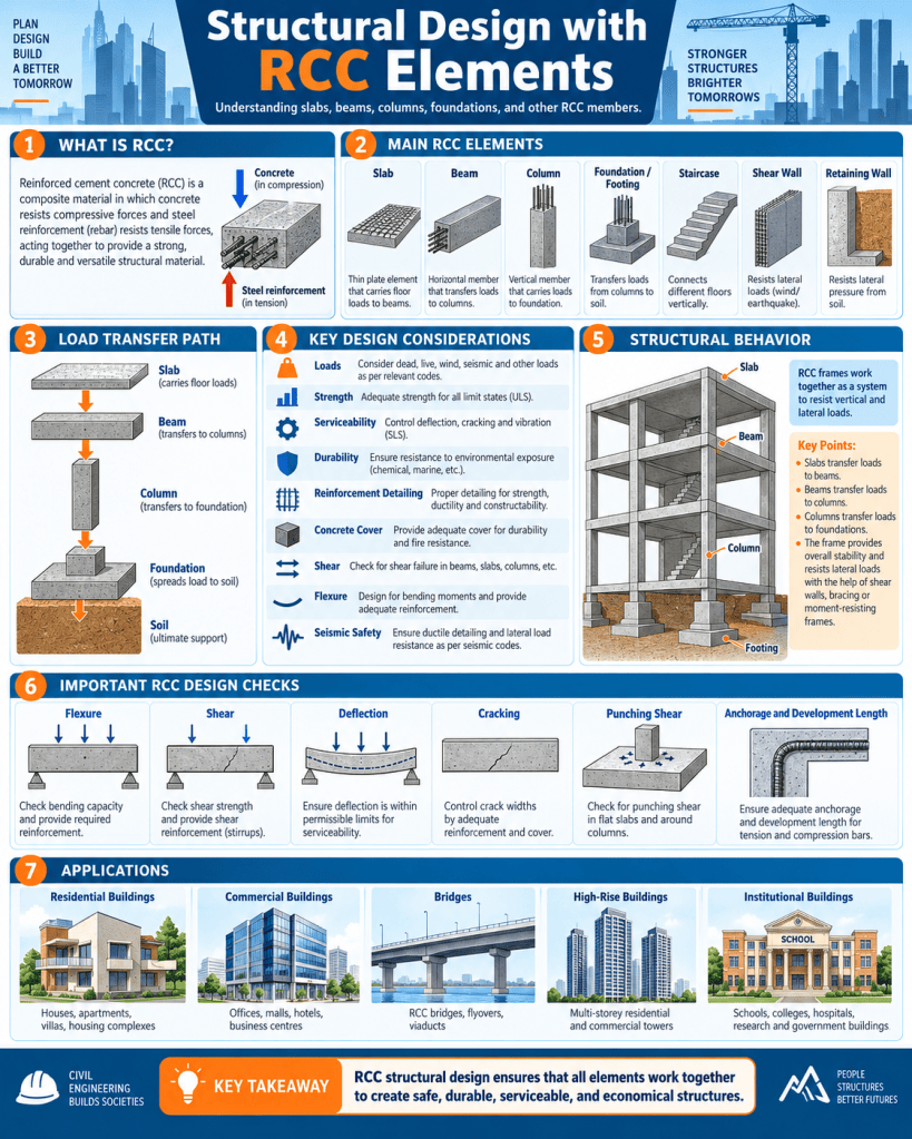
Reinforced Cement Concrete (RCC) is one of the most widely used structural systems in buildings and infrastructure. It combines the compressive strength of concrete with the tensile strength of steel reinforcement, allowing structural members to resist different types of loads safely and efficiently. RCC is extensively used in residential buildings, commercial complexes, bridges, industrial structures, institutional buildings, retaining walls, water tanks, and high-rise construction.

Structural design with RCC elements involves determining suitable sizes, reinforcement, detailing, and arrangement of members so that the structure remains safe, serviceable, durable, and economical throughout its intended life. The main RCC elements include slabs, beams, columns, foundations, staircases, shear walls, and retaining walls. These components work together to transfer loads from the building to the ground.

Basic Principle of RCC

Concrete performs very well in compression but has relatively low tensile strength. Steel, on the other hand, has excellent tensile capacity. In RCC, steel reinforcement is placed in regions where tension is expected.

The bond between concrete and steel allows them to act together as a composite structural material.

The basic load path in a framed building is generally:

Slab → Beam → Column → Foundation → Soil

Each structural component must therefore be designed not only individually but also as part of an integrated load-transfer system.

Objectives of RCC Structural Design

The main objectives of RCC design are to ensure:

  • structural safety;
  • adequate strength;
  • stability;
  • serviceability;
  • durability;
  • fire resistance;
  • economy;
  • constructability.

A structure should not collapse under design loads, but it should also not experience excessive cracking, vibration, or deflection during normal use.

Loads Considered in RCC Design

Structural design begins with identifying the loads acting on the building.

Dead Load

Dead load includes the permanent weight of:

  • RCC members;
  • walls;
  • floor finishes;
  • roofing;
  • fixed equipment.

Live Load

Live load includes temporary or movable loads caused by:

  • occupants;
  • furniture;
  • storage;
  • movable equipment.

Wind Load

Wind produces lateral pressure and suction on buildings.

It becomes particularly important for tall buildings, large roofs, and exposed structures.

Earthquake Load

Earthquake forces result from ground motion and structural inertia.

Seismic design is especially important in earthquake-prone regions.

Other Loads

Depending on the structure, designers may also consider:

  • snow loads;
  • soil pressure;
  • water pressure;
  • temperature effects;
  • impact;
  • equipment vibration.

Limit State Design of RCC

Modern RCC structures are commonly designed using the Limit State Method.

Two broad categories are checked:

Ultimate Limit State

This concerns safety against failure due to:

  • bending;
  • shear;
  • compression;
  • torsion;
  • instability;
  • collapse.

Serviceability Limit State

This concerns satisfactory performance under normal use.

Typical checks include:

  • deflection;
  • cracking;
  • vibration;
  • durability.

The structure must satisfy both.

RCC Slabs

A slab is a horizontal structural element used to form floors and roofs.

Slabs transfer loads to beams, walls, or directly to columns.

Common slab types include:

  • one-way slabs;
  • two-way slabs;
  • flat slabs;
  • cantilever slabs.

One-Way Slab

A one-way slab primarily bends and transfers load in one direction.

This usually occurs when the slab is supported on two opposite sides or when the longer span is significantly greater than the shorter span.

Main reinforcement is generally placed along the shorter span.

Distribution reinforcement is provided perpendicular to it.

Two-Way Slab

A two-way slab transfers load in both directions.

It is commonly used when the slab is supported on all four sides and the plan dimensions are relatively comparable.

Reinforcement is provided in both directions.

Two-way action can reduce bending moments compared with one-way action.

Flat Slab

A flat slab is supported directly by columns without conventional beams.

Its advantages include:

  • reduced structural depth;
  • flexible floor planning;
  • simpler service routing;
  • clean ceiling appearance.

However, punching shear around columns becomes an important design concern.

Drop panels or column heads may be used where necessary.

Cantilever Slab

A cantilever slab is fixed at one end and free at the other.

Typical applications include:

  • balconies;
  • sunshades;
  • canopies.

The main tensile reinforcement is generally placed near the top surface close to the support.

RCC Beams

Beams transfer loads from slabs and walls to columns or other supports.

They primarily resist:

  • bending moments;
  • shear forces;
  • sometimes torsion.

In a simply supported beam under downward gravity loading, the bottom region is generally in tension and the top region in compression.

Beam Reinforcement

Typical beam reinforcement includes:

Main Bars

These resist flexural tension.

Stirrups

Stirrups provide shear resistance and hold longitudinal reinforcement in position.

Top Bars

Top reinforcement is particularly important at supports in continuous beams and cantilevers.

Bottom Bars

Bottom reinforcement is commonly required at midspan in simply supported beams.

Proper anchorage and development length are essential.

Simply Supported Beams

A simply supported beam rests on supports at both ends.

The maximum positive bending moment generally occurs near midspan.

These beams are conceptually simple but are less common in monolithic RCC frames where continuity is usually present.

Continuous Beams

Continuous beams extend over more than two supports.

They develop:

  • positive moments in spans;
  • negative moments over supports.

Reinforcement must therefore be arranged appropriately in both top and bottom zones.

Cantilever Beams

Cantilever beams are fixed at one end and free at the other.

The top surface near the fixed support is usually in tension under downward load.

Cantilevers are used for balconies, canopies, projections, and architectural features.

RCC Columns

Columns are vertical structural members that transfer loads from beams and slabs to foundations.

They are mainly subjected to compression but may also experience bending moments.

Columns may be:

  • square;
  • rectangular;
  • circular;
  • L-shaped;
  • T-shaped.

Their design depends on:

  • axial load;
  • bending moment;
  • slenderness;
  • reinforcement ratio;
  • support conditions.

Short and Slender Columns

A short column is less sensitive to buckling and generally fails by compression or material strength.

A slender column can experience significant additional bending due to lateral deflection.

Slenderness must therefore be checked carefully.

Column Reinforcement

Column reinforcement includes:

Longitudinal Bars

These carry axial and bending forces.

Lateral Ties

These hold the longitudinal reinforcement in position and provide confinement.

Spiral Reinforcement

Circular columns may use helical reinforcement.

Good confinement improves ductility, particularly under seismic loading.

Beam-Column Joints

Beam-column joints are critical areas in RCC frames.

They transfer forces between horizontal and vertical structural elements.

Under earthquake loading, these joints may experience high shear stresses and repeated load reversals.

Good detailing includes:

  • proper anchorage;
  • adequate confinement;
  • closely spaced ties;
  • correct bar continuity.

Poor joint detailing can lead to brittle failure.

RCC Foundations

Foundations transfer column and wall loads safely to the soil.

Common RCC foundations include:

  • isolated footings;
  • combined footings;
  • strap footings;
  • raft foundations;
  • pile caps.

Foundation design depends heavily on soil bearing capacity and settlement.

Isolated Footing

An isolated footing supports a single column.

Its area is selected so that soil pressure remains within allowable limits.

The footing must be checked for:

  • bending;
  • one-way shear;
  • punching shear;
  • bearing.

Combined Footing

A combined footing supports two or more columns.

It is often used when:

  • columns are close together;
  • property boundaries restrict footing size;
  • individual footings would overlap.

The footing may be rectangular or trapezoidal.

Raft Foundation

A raft or mat foundation supports many columns over a large slab.

It is useful when:

  • soil bearing capacity is low;
  • columns are closely spaced;
  • settlement needs to be controlled.

Rafts distribute loads over a large area.

Pile Caps

Pile caps connect groups of piles and transfer column loads to them.

They are designed to resist:

  • bending;
  • shear;
  • localized stresses.

Pile caps must be carefully detailed because loads are concentrated around pile locations.

RCC Staircases

RCC staircases may be designed as:

  • waist-slab stairs;
  • folded plate stairs;
  • cantilever stairs;
  • stair slabs supported on beams.

The stair must safely carry:

  • self-weight;
  • finishes;
  • live load.

Reinforcement follows the direction of structural spanning.

Shear Walls

Shear walls are vertical RCC elements designed to resist lateral loads caused by wind and earthquakes.

They are commonly used in:

  • high-rise buildings;
  • apartment towers;
  • core walls;
  • lift and stair enclosures.

Shear walls provide:

  • high lateral stiffness;
  • reduced building sway;
  • improved seismic resistance.

Their location should be carefully planned to reduce torsional effects.

Retaining Walls

Retaining walls resist lateral earth pressure.

Common RCC retaining wall types include:

  • cantilever retaining walls;
  • counterfort retaining walls;
  • basement walls.

The wall must be designed for:

  • earth pressure;
  • surcharge;
  • water pressure;
  • sliding;
  • overturning;
  • bearing.

Drainage behind retaining walls is essential to reduce hydrostatic pressure.

Reinforcement Detailing

Good reinforcement detailing is essential for structural performance.

Important aspects include:

  • bar spacing;
  • anchorage;
  • development length;
  • lap length;
  • cover;
  • stirrup spacing;
  • curtailment;
  • joint detailing.

Incorrect detailing can cause failure even when member dimensions are adequate.

Development Length

Reinforcement must extend sufficiently into concrete so that bond stresses can safely transfer force between steel and concrete.

This required embedded length is called development length.

Insufficient anchorage can cause bar pull-out or bond failure.

Lap Splices

When reinforcement bars cannot be provided in one continuous length, lap splices are used.

The lap length depends on:

  • bar diameter;
  • concrete strength;
  • steel grade;
  • type of stress.

Splices should be located away from highly stressed zones whenever possible.

Concrete Cover

Concrete cover is the distance between the reinforcement and the concrete surface.

It provides protection against:

  • corrosion;
  • fire;
  • weather exposure.

Insufficient cover reduces durability, while excessive cover can contribute to wider surface cracking.

Shear Design

Shear forces can produce diagonal cracking in beams and slabs.

Shear resistance is provided by:

  • concrete;
  • stirrups;
  • bent bars in some systems.

In beams, vertical or inclined stirrups are commonly used.

Shear failure is potentially brittle and must be prevented.

Flexural Design

Flexural design ensures that the member can resist bending moments.

For an under-reinforced RCC beam, steel should yield before concrete crushes.

This provides more ductile behavior and warning before failure.

Over-reinforced sections are generally avoided because they may fail suddenly through concrete crushing.

Torsion

Torsion occurs when a structural member twists about its longitudinal axis.

It may occur in:

  • edge beams;
  • curved structures;
  • irregular framing.

Torsion reinforcement generally consists of closed stirrups and longitudinal bars.

Punching Shear

Punching shear is particularly important in flat slabs and footings.

It occurs around concentrated supports such as columns.

The slab may fail around the column perimeter if adequate thickness or reinforcement is not provided.

Measures may include:

  • increasing slab thickness;
  • providing drop panels;
  • increasing column dimensions;
  • using shear reinforcement.

Deflection Control

Excessive deflection can cause:

  • cracked partitions;
  • uneven floors;
  • visual problems;
  • serviceability issues.

Deflection is influenced by:

  • span;
  • depth;
  • loading;
  • reinforcement;
  • cracking;
  • long-term creep.

Adequate member depth is one of the simplest ways to control deflection.

Crack Control

Cracking in RCC can result from:

  • flexure;
  • shrinkage;
  • temperature changes;
  • settlement;
  • corrosion.

Controlled cracking is expected in reinforced concrete, but crack widths should remain within acceptable limits.

Proper reinforcement distribution and curing help reduce cracking.

Durability

Durability is essential for long service life.

Important factors include:

  • adequate cover;
  • low-permeability concrete;
  • proper compaction;
  • proper curing;
  • suitable materials;
  • environmental exposure.

Poor durability may lead to reinforcement corrosion and concrete spalling.

Concrete Grade

Concrete grade indicates its characteristic compressive strength.

The selected grade depends on:

  • structural requirement;
  • exposure condition;
  • durability;
  • applicable design codes.

Higher strength concrete may be used for heavily loaded columns, high-rise buildings, and specialized structures.

Reinforcement Steel

Reinforcement steel should provide:

  • adequate yield strength;
  • ductility;
  • bond;
  • weldability where required.

Deformed bars are commonly used because their ribs improve bond with concrete.

Formwork Considerations

RCC elements require formwork until concrete develops sufficient strength.

Formwork must provide:

  • correct dimensions;
  • alignment;
  • stability;
  • smooth finish;
  • leak resistance.

Poor formwork can result in dimensional errors and honeycombing.

Concreting

Concrete should be properly:

  • batched;
  • mixed;
  • transported;
  • placed;
  • compacted;
  • cured.

Segregation should be avoided.

Mechanical vibrators are commonly used to remove entrapped air.

Curing

Curing allows cement hydration to continue.

Proper curing improves:

  • compressive strength;
  • durability;
  • water resistance;
  • crack control.

Inadequate curing can significantly reduce concrete quality.

Construction Joints

Construction joints are required when concrete placement is interrupted.

They should be placed at suitable structural locations.

The old concrete surface should be cleaned and prepared before placing new concrete.

Ductile Detailing

In earthquake-resistant RCC design, ductility is critical.

Important principles include:

  • strong-column weak-beam behavior;
  • closely spaced ties near joints;
  • adequate anchorage;
  • confinement of column ends;
  • controlled lap locations.

The aim is to allow energy dissipation without sudden collapse.

Strong-Column Weak-Beam Concept

In seismic design, it is preferable for beams to yield before columns.

If columns fail first, an entire storey may collapse.

Therefore, columns are often designed to remain stronger than connected beams.

Structural Regularity

Regular structural layouts generally perform better during earthquakes.

Irregularities may occur in:

  • plan;
  • elevation;
  • stiffness;
  • mass distribution.

Examples include soft storeys, floating columns, large setbacks, and asymmetrical cores.

These conditions require special analysis and detailing.

Service Integration

Structural design should be coordinated with building services.

Openings for:

  • ducts;
  • pipes;
  • electrical services;

should not be cut into beams or slabs without structural approval.

Unplanned openings can significantly weaken structural members.

Quality Control

Important quality checks include:

  • reinforcement diameter and spacing;
  • concrete cover;
  • formwork alignment;
  • slump;
  • concrete strength testing;
  • vibration;
  • curing;
  • dimensions.

Good site supervision is essential.

Common RCC Defects

Typical defects include:

Honeycombing

Caused by poor compaction or congested reinforcement.

Cracks

May result from structural stress, shrinkage, thermal effects, or settlement.

Corrosion

Occurs when moisture and aggressive chemicals reach reinforcement.

Spalling

Concrete cover may break away due to reinforcement corrosion or impact.

Excessive Deflection

May result from inadequate stiffness, overloading, or poor design.

Sustainability in RCC Structural Design

RCC structures can be made more sustainable by reducing unnecessary material use.

Strategies include:

  • structural optimization;
  • blended cement;
  • supplementary cementitious materials;
  • recycled aggregates where suitable;
  • reusable formwork;
  • efficient reinforcement detailing;
  • long-life design.

Durable design reduces the need for repair and replacement.

Importance of Structural Coordination

RCC design should be coordinated closely with architectural planning.

Important issues include:

  • column positions;
  • beam depths;
  • slab thickness;
  • floor heights;
  • service shafts;
  • openings;
  • façade systems.

Early coordination reduces later conflicts and improves structural efficiency.

Conclusion

Structural design with RCC elements requires a systematic understanding of how slabs, beams, columns, foundations, staircases, shear walls, and retaining walls work together. Each component plays a specific role in transferring loads safely through the structure to the ground.

Slabs distribute floor loads, beams transfer these loads to columns, columns carry them vertically, and foundations spread them to the soil. Shear walls provide resistance to lateral loads, while reinforcement ensures that concrete can safely resist tensile forces.

Successful RCC design depends on more than calculations. Proper reinforcement detailing, adequate cover, good formwork, careful concreting, compaction, curing, and quality control are equally important.

When structural design, material selection, construction practice, durability, and seismic detailing are properly integrated, RCC provides a safe, strong, durable, adaptable, and economical structural system suitable for a wide variety of modern buildings and infrastructure.

Daily writing prompt
How do you write what people actually want to read?

Structural Design: Elastic Design vs Limit State Design

Introduction

Structural design is the process of determining the size, shape, material, reinforcement, and arrangement of structural members so that a building or infrastructure system can safely resist the loads acting on it throughout its service life. The designer must ensure that the structure is not only strong enough to avoid collapse but also sufficiently stiff and durable to remain usable under normal conditions.

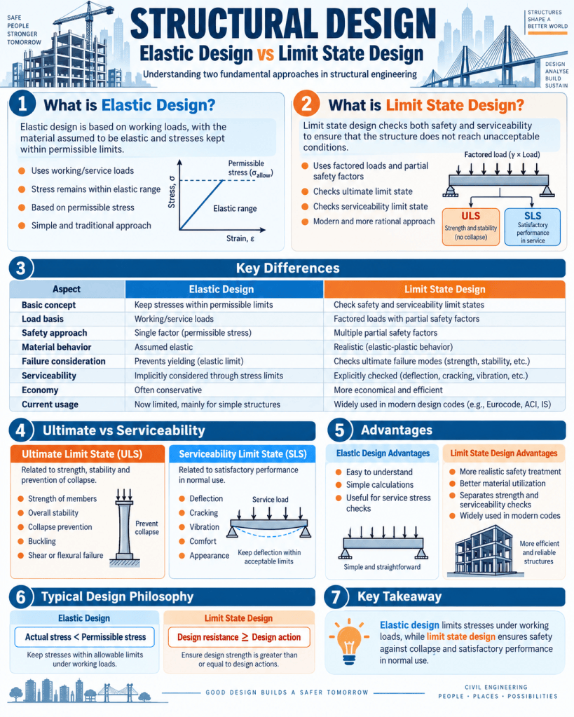
Two important approaches used in structural engineering are Elastic Design and Limit State Design. Elastic design is based mainly on the assumption that structural materials behave elastically under working loads and that stresses should remain within permissible values. Limit State Design, on the other hand, evaluates a structure against clearly defined failure and serviceability conditions and uses partial safety factors for loads and materials.

The shift from elastic or working stress methods to limit state design represents an important development in structural engineering because it provides a more realistic treatment of material behavior, loading uncertainty, structural safety, and serviceability.

Concept of Elastic Design

Elastic design is based on the principle that a structural member should remain within the elastic range when subjected to normal working loads.

In the elastic range, stress is approximately proportional to strain, following Hooke’s law:

Stress ∝ Strain

or

σ = Eε

where:

  • σ = stress,
  • E = modulus of elasticity,
  • ε = strain.

If the applied load is removed while the material remains within the elastic range, the member returns approximately to its original shape.

Elastic design is closely associated with the Working Stress Method, in which allowable or permissible stresses are obtained by dividing the material strength by a factor of safety.

Working Stress Concept

In working stress design, the loads expected during normal use are called working loads or service loads.

The calculated stress under these loads should not exceed the permissible stress.

A simplified expression is:

Permissible Stress = Material Strength / Factor of Safety

For example, if a material has a specified strength of 300 MPa and a factor of safety of 1.5 is used:

Permissible Stress = 300 / 1.5 = 200 MPa

The member is then proportioned so that the calculated working stress remains below 200 MPa.

Assumptions of Elastic Design

Elastic design generally assumes that:

  • materials behave elastically under service loads;
  • stress and strain have a linear relationship;
  • sections remain within permissible stress limits;
  • factors of safety are applied mainly to material strength;
  • the structural response is predictable through elastic analysis.

These assumptions make calculations relatively straightforward.

Advantages of Elastic Design

Elastic design offers several benefits.

Simplicity

The method is conceptually simple and easy to understand.

Service Load Focus

Because calculations are performed directly at working loads, stresses and elastic deformations can be assessed easily.

Suitable for Certain Materials and Structures

Elastic methods remain useful in areas where service stress control is particularly important.

Long Historical Use

Many existing buildings and bridges were successfully designed using elastic or working stress principles.

Limitations of Elastic Design

The main limitation is that the method does not always represent actual structural behavior near failure.

Materials such as reinforced concrete and structural steel can develop significant reserve strength beyond initial elastic behavior.

Elastic design may therefore be overly conservative in some cases and may not distribute safety as consistently across different types of loads and materials.

Other limitations include:

  • limited representation of ultimate failure;
  • single overall safety approach;
  • less rational treatment of load variability;
  • inability to make full use of plastic behavior;
  • possible uneconomical member sizes.

Concept of Limit State Design

Limit State Design (LSD) is a modern approach in which a structure is designed so that it does not reach any unacceptable condition during its intended life.

These unacceptable conditions are called limit states.

A limit state represents the point beyond which a structure no longer satisfies the required performance criteria.

Limit states are broadly classified into:

  1. Ultimate Limit States
  2. Serviceability Limit States

Ultimate Limit State

The Ultimate Limit State, or ULS, concerns structural safety against collapse or major failure.

Examples include:

  • flexural failure;
  • shear failure;
  • compression failure;
  • buckling;
  • overturning;
  • sliding;
  • loss of equilibrium;
  • fatigue in relevant structures;
  • rupture of structural members.

The structure must possess adequate strength and stability under factored loads.

Serviceability Limit State

The Serviceability Limit State, or SLS, concerns the satisfactory functioning of the building under normal use.

Typical serviceability issues include:

  • excessive deflection;
  • excessive cracking;
  • vibration;
  • settlement;
  • water leakage;
  • discomfort;
  • unacceptable appearance.

A structure may be safe against collapse but still be unsuitable for use if it deflects excessively or develops severe cracking.

Thus, Limit State Design explicitly checks both safety and usability.

Characteristic Loads and Strengths

Limit state design generally uses characteristic values of loads and material strengths.

Characteristic loads may include:

  • dead load;
  • live load;
  • wind load;
  • earthquake load;
  • snow load;
  • other environmental actions.

Characteristic strength refers to a statistically defined material strength below which only a specified proportion of test results is expected to fall.

These characteristic values are then modified using partial safety factors.

Partial Safety Factors

One of the key features of Limit State Design is the use of separate safety factors for:

  • loads;
  • materials.

This is more refined than applying a single overall factor of safety.

The design action may be expressed conceptually as:

Design Load = Characteristic Load × Load Factor

Similarly:

Design Strength = Characteristic Strength / Material Safety Factor

The exact factors depend on the applicable design code, load combination, material, and limit state.

Load Combinations

A structure rarely experiences maximum values of all loads simultaneously.

Limit State Design therefore considers various load combinations.

Typical combinations may involve:

  • dead load + live load;
  • dead load + wind load;
  • dead load + live load + wind load;
  • dead load + earthquake load.

Different combinations are checked because each may produce a different critical response.

Elastic Analysis Within Limit State Design

It is important to understand that Limit State Design does not necessarily mean elastic analysis is abandoned.

Many structures are still analyzed using elastic structural analysis to determine:

  • bending moments;
  • shear forces;
  • axial forces;
  • reactions.

However, the design of members is then checked using limit state principles and factored values.

Thus, elastic analysis and elastic design are not always identical concepts.

Elastic Design of Reinforced Concrete

In traditional working stress design of reinforced concrete, both concrete and steel stresses are kept within permissible limits under working loads.

Because concrete is weak in tension, tensile forces are primarily resisted by reinforcement.

The method assumes elastic behavior and generally produces larger sections or more conservative stress levels compared with modern ultimate strength approaches.

Limit State Design of Reinforced Concrete

In Limit State Design, reinforced concrete members are designed using their behavior closer to ultimate conditions.

For example, a reinforced concrete beam is checked for:

  • ultimate bending strength;
  • shear resistance;
  • reinforcement requirements;
  • deflection;
  • cracking.

The method recognizes nonlinear concrete behavior and allows more realistic use of reinforcement and concrete strength.

Structural Steel and Elastic Design

Steel behaves approximately elastically up to its yield point.

Traditional elastic steel design limits stresses below yield under service loads.

This provides straightforward analysis but may not make full use of steel’s capacity beyond first yield.

Limit State Design of Steel

Limit state steel design checks structural members against conditions such as:

  • yielding;
  • buckling;
  • local buckling;
  • lateral torsional buckling;
  • connection failure;
  • fatigue;
  • excessive deflection.

Modern steel design therefore addresses both material strength and instability.

Factor of Safety Philosophy

The difference between the two methods can be better understood through their safety philosophy.

Elastic Design

Elastic design generally applies safety by limiting allowable stress.

The main idea is:

Actual working stress < Permissible stress

Limit State Design

Limit State Design applies safety separately to loads and material resistance.

The main concept is:

Design resistance ≥ Design action

This provides a more transparent and consistent approach to uncertainty.

Comparison: Elastic Design vs Limit State Design

AspectElastic DesignLimit State Design
Basic conceptKeep stresses within permissible elastic limitsPrevent specified ultimate and serviceability limit states
LoadsWorking/service loadsFactored loads for ULS and service loads for SLS
Material strengthReduced by overall factor of safetyCharacteristic strength modified by material factors
Structural behaviorMainly elasticIncludes ultimate and service behavior
Safety factorsUsually global or permissible-stress basedPartial factors for loads and materials
Failure predictionLess directExplicitly considers failure modes
ServiceabilityOften inherent in working stress checkChecked separately
EconomyOften more conservativeUsually more efficient
Modern usageLimited/special applicationsWidely used in modern codes

Example of a Beam

Consider a beam carrying permanent and imposed loads.

Under elastic design, the designer calculates bending moment using service loads and determines the bending stress.

The calculated stress must remain below the permissible stress.

In Limit State Design, the procedure is different.

First, ultimate load combinations are generated using appropriate partial factors. The beam is designed so that its ultimate moment resistance exceeds the factored bending moment.

Then separate checks are performed for serviceability, such as:

  • deflection;
  • cracking;
  • vibration.

This separates collapse prevention from normal-use performance.

Strength and Serviceability

One of the most important principles of modern structural design is that strength alone is not sufficient.

For example, a floor beam might be strong enough to avoid collapse but may vibrate excessively when people walk across it.

Similarly, an RCC slab may have adequate ultimate capacity but may develop excessive cracking.

Limit State Design directly recognizes this by requiring separate ULS and SLS checks.

Reliability-Based Approach

Limit State Design is more closely connected with probabilistic thinking.

Loads and material strengths are not perfectly predictable.

For example:

  • actual live loads vary;
  • material strength varies between batches;
  • dimensions may differ slightly;
  • workmanship varies;
  • environmental effects are uncertain.

Partial safety factors are intended to account for such uncertainties in a rational way.

Ductility

Ductility is another important consideration.

A ductile structure can deform significantly before failure, providing warning and redistributing forces.

Modern limit state codes often include detailing requirements to achieve ductile behavior, especially in earthquake-resistant design.

This is particularly important for:

  • reinforced concrete frames;
  • steel moment frames;
  • seismic structures.

Economy of Limit State Design

Because Limit State Design makes better use of material strength and provides a more refined safety approach, it can often produce more economical structures.

Possible benefits include:

  • smaller member dimensions;
  • optimized reinforcement;
  • efficient material utilization;
  • better load combination treatment.

However, economy should never compromise durability or serviceability.

Role of Codes and Standards

Structural design must follow applicable national or international standards.

Design codes specify:

  • loads;
  • load combinations;
  • material strengths;
  • safety factors;
  • detailing rules;
  • serviceability limits.

Different jurisdictions may use different terminology, coefficients, and calculation methods.

Therefore, designers should always work with the current applicable code rather than relying on generic values.

Elastic Design in Present Practice

Although Limit State Design dominates modern structural engineering, elastic concepts remain extremely important.

Elastic analysis is still used for:

  • structural response calculations;
  • serviceability analysis;
  • stress distribution;
  • preliminary sizing;
  • certain specialized design situations.

Thus, the development of Limit State Design did not make elasticity irrelevant.

Instead, it placed elastic analysis within a broader safety framework.

Limit State Design in Seismic Engineering

Seismic design particularly demonstrates the importance of limit state thinking.

A structure may be expected to experience different performance levels during different earthquake intensities.

Possible objectives include:

  • limited damage during minor earthquakes;
  • repairable damage during moderate events;
  • prevention of collapse during severe earthquakes.

This approach cannot be captured adequately through a simple permissible-stress check alone.

Durability as a Design Consideration

Modern structural design also recognizes that a structure must remain safe throughout its intended life.

Durability issues include:

  • reinforcement corrosion;
  • carbonation;
  • chloride exposure;
  • weathering;
  • moisture;
  • chemical attack.

Limit state-based codes often include minimum requirements for cover, crack control, materials, and exposure conditions.

Construction Quality

No design approach can compensate for poor construction.

Even a well-designed structure can perform poorly if:

  • reinforcement is misplaced;
  • concrete is inadequately compacted;
  • bolts are improperly tightened;
  • welds are defective;
  • member dimensions are incorrect.

Quality control and inspection therefore remain essential under both design philosophies.

Advantages of Limit State Design

Major advantages include:

  • rational safety treatment;
  • consideration of multiple failure modes;
  • separate serviceability checks;
  • better representation of actual material behavior;
  • efficient use of materials;
  • compatibility with modern reliability concepts.

Limitations of Limit State Design

Despite its benefits, Limit State Design can be more complex than basic elastic design.

It requires:

  • multiple load combinations;
  • separate ULS and SLS checks;
  • detailed understanding of material behavior;
  • careful code interpretation.

For complex structures, computer-based analysis is often used.

Importance for Architecture and Construction

Architects and construction professionals should understand these design concepts even when detailed calculations are performed by structural engineers.

Structural design influences:

  • column spacing;
  • beam depth;
  • slab thickness;
  • floor-to-floor height;
  • structural form;
  • material selection;
  • cost.

Early coordination between architectural and structural design can therefore produce more efficient buildings.

Conclusion

Elastic Design and Limit State Design represent two important approaches to structural engineering. Elastic Design is based primarily on keeping stresses under service loads within permissible elastic limits. It is conceptually simple and has a long history of successful use, but it does not fully describe structural behavior near failure.

Limit State Design provides a broader framework by checking both Ultimate Limit States and Serviceability Limit States. It uses partial safety factors for loads and materials, evaluates different failure modes, and recognizes that a structure must be safe against collapse while also remaining functional, comfortable, and durable during normal use.

The basic distinction can therefore be summarized as follows:

Elastic Design asks: “Are the stresses under working loads within allowable limits?”

Limit State Design asks: “Is the structure safe against failure and satisfactory in normal service under all relevant design conditions?”

Modern structural engineering largely adopts the second philosophy because it provides a more comprehensive, realistic, and economical basis for designing reinforced concrete, steel, and other structural systems.

Daily writing prompt
How do you write what people actually want to read?

Alternative & Earth-Based Building Materials: CSEB and Bamboo

Introduction

Alternative and earth-based building materials are becoming increasingly important in sustainable architecture and construction. Conventional materials such as fired clay bricks, cement, steel, and concrete are widely used because of their strength, availability, and established construction practices. However, their production can require large amounts of energy, natural resources, and transportation. In response, architects, engineers, and builders are exploring materials that are locally available, renewable, low in embodied energy, affordable, and environmentally responsible.

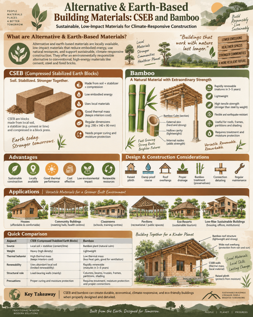
Among the most promising alternatives are Compressed Stabilized Earth Blocks (CSEB) and bamboo. CSEB combines earth with a small quantity of stabilizer and mechanical compression to produce strong masonry units. Bamboo is a rapidly renewable natural material with high tensile strength and a long history of use in houses, bridges, roofs, scaffolding, and furniture.

Both materials demonstrate how traditional knowledge can be combined with modern engineering to create durable, efficient, and climate-responsive buildings.

What Are Alternative Building Materials?

Alternative building materials are materials used as substitutes for conventional construction products when they offer environmental, economic, social, or technical advantages.

Examples include:

  • compressed earth blocks;
  • stabilized mud blocks;
  • rammed earth;
  • adobe;
  • bamboo;
  • straw bale;
  • recycled aggregates;
  • fly-ash blocks;
  • lime-based materials;
  • recycled timber;
  • agricultural-waste panels.

The choice of material depends on local climate, available resources, required structural performance, workmanship, maintenance, and building regulations.

Earth as a Building Material

Earth is one of the oldest construction materials used by humans. Traditional earth construction techniques include adobe, cob, rammed earth, mud masonry, and earthen plaster.

Earth offers several advantages:

  • local availability;
  • relatively low embodied energy;
  • good thermal mass;
  • low transportation requirements;
  • recyclability;
  • affordability.

However, untreated earth can have limitations such as low water resistance, shrinkage cracking, and variable strength. Stabilization and controlled production methods help improve its performance.

Compressed Stabilized Earth Blocks

Compressed Stabilized Earth Blocks, or CSEB, are masonry units made from suitable soil mixed with a controlled amount of stabilizer and compacted under pressure.

Typical ingredients include:

  • soil;
  • sand where required;
  • cement or lime;
  • water.

The mixture is placed in a manual or mechanical press and compressed into blocks of uniform size.

Unlike fired bricks, CSEB units are generally not fired in kilns.

Soil Selection for CSEB

The performance of a CSEB depends strongly on soil composition.

Suitable soil generally contains a balanced mixture of:

  • gravel;
  • sand;
  • silt;
  • clay.

Too much clay can cause shrinkage and cracking, while too much sand may reduce cohesion.

Before production, soil should be tested for:

  • grain-size distribution;
  • plasticity;
  • moisture content;
  • organic matter;
  • stabilizer requirement.

Locally available soil may often be modified by adding sand or other materials.

Stabilization

Stabilization improves the strength and water resistance of earth blocks.

Common stabilizers include:

Cement

Cement is widely used because it improves compressive strength and resistance to moisture.

Lime

Lime is especially useful for certain clay-rich soils and can improve workability and long-term stability.

Combined Stabilizers

In some cases, cement and lime may be used together.

The amount of stabilizer should be optimized because excessive use increases cost and embodied energy.

Manufacturing Process of CSEB

A typical CSEB production process includes:

  1. selecting suitable soil;
  2. removing organic matter and oversized particles;
  3. sieving the soil;
  4. proportioning soil and stabilizer;
  5. dry mixing;
  6. adding controlled water;
  7. placing the mixture in a block press;
  8. compressing the block;
  9. removing the block carefully;
  10. curing under controlled conditions.

Proper curing is particularly important for cement-stabilized blocks.

CSEB Block Presses

Blocks may be produced using:

  • manual presses;
  • semi-mechanical presses;
  • hydraulic machines.

Manual presses are useful for small-scale and community-based construction, while hydraulic machines provide higher production rates and more consistent compaction.

Advantages of CSEB

CSEB offers several benefits.

Lower Energy Requirement

Because blocks are not fired in conventional brick kilns, production generally requires less energy.

Local Material Use

Soil can often be obtained near the construction site, reducing transportation.

Uniform Dimensions

Mechanical compression creates regular blocks, reducing mortar consumption and improving construction accuracy.

Thermal Performance

Earth walls have high thermal mass, helping moderate indoor temperature fluctuations.

Reduced Waste

Broken or rejected blocks can sometimes be crushed and reused as earth material.

Architectural Character

Exposed earth blocks provide a natural texture and color.

Limitations of CSEB

CSEB also has limitations.

These include:

  • need for proper soil testing;
  • sensitivity to poor curing;
  • potential water damage if detailing is inadequate;
  • requirement for skilled production control;
  • need for protective design in heavy rainfall regions.

CSEB walls should not be continuously exposed to standing water.

Construction Detailing for CSEB

Good detailing is essential for long-lasting earth buildings.

Important measures include:

  • raised plinths;
  • damp-proof courses;
  • roof overhangs;
  • proper drainage;
  • protected wall bases;
  • suitable plaster or surface treatment where required.

The principle often summarized as “good boots and a good hat” is particularly relevant to earth buildings: protect the base from water and provide adequate roof protection.

Mortar for CSEB

Mortar should be compatible with the blocks.

Possible mortars include:

  • stabilized earth mortar;
  • cement-lime mortar;
  • thin joint mortar where suitable.

Very strong cement-rich mortar may be unnecessary and can create compatibility problems.

Structural Use of CSEB

CSEB can be used for:

  • load-bearing walls;
  • non-load-bearing partitions;
  • infill walls;
  • low-rise buildings;
  • community facilities;
  • residential construction.

Structural use should be based on tested block strength, wall thickness, building height, and applicable design requirements.

Bamboo as a Building Material

Bamboo is a fast-growing natural material that has been used for construction for centuries, especially in tropical and subtropical regions.

Although commonly called a wood material, bamboo is botanically a grass.

Its structural advantages include:

  • high tensile strength;
  • low density;
  • flexibility;
  • rapid renewability;
  • ease of cutting;
  • good performance in lightweight structures.

Bamboo can be used in both traditional and engineered forms.

Characteristics of Bamboo

Bamboo has a hollow cylindrical form divided by nodes.

The fibers run mainly along the length of the culm, providing high longitudinal strength.

Its performance depends on:

  • species;
  • age;
  • moisture content;
  • diameter;
  • wall thickness;
  • harvesting method;
  • treatment.

Mature bamboo is generally preferred for structural use.

Applications of Bamboo

Bamboo can be used for:

  • columns;
  • roof trusses;
  • rafters;
  • purlins;
  • floor systems;
  • wall frames;
  • scaffolding;
  • bridges;
  • partitions;
  • furniture;
  • screens and shading devices.

Modern engineered bamboo products expand these possibilities further.

Bamboo Structural Systems

Post-and-Beam Systems

Bamboo culms can act as columns and beams in lightweight buildings.

Roof Trusses

Bamboo is suitable for roof trusses because of its light weight and ability to resist tensile forces.

Space Frames

Properly connected bamboo members can create lightweight three-dimensional structures.

Curved Structures

Bamboo’s natural flexibility allows the creation of curved roofs, pavilions, and organic architectural forms.

Bamboo Connections

Connections are one of the most challenging parts of bamboo construction.

Because bamboo is hollow and can split, conventional timber connections may not always work effectively.

Common connection methods include:

  • rope or fiber lashing;
  • bolts;
  • dowels;
  • steel plates;
  • clamps;
  • threaded rods;
  • filled joint systems;
  • specially designed connectors.

The connection should distribute forces without crushing or splitting the bamboo.

Lashing Connections

Traditional bamboo buildings often use natural fiber or rope lashings.

Advantages include:

  • simplicity;
  • flexibility;
  • low cost;
  • ease of replacement.

However, lashing durability and long-term performance must be considered.

Bolted Connections

Bolts can provide stronger mechanical connections.

To reduce splitting, designers may use:

  • washers;
  • internal fillers;
  • reinforced nodes;
  • steel sleeves.

Bolt holes should be carefully located and drilled.

Bamboo Treatment

Untreated bamboo is vulnerable to insects, fungi, and decay.

Treatment is therefore essential for durable construction.

Common methods include:

  • borax-boric acid treatment;
  • soaking;
  • pressure treatment;
  • heat treatment;
  • surface coatings.

The selected treatment should be suitable for the intended exposure conditions.

Protection from Moisture

Bamboo should be kept away from prolonged ground contact and standing water.

Good detailing includes:

  • raised foundations;
  • steel or concrete base connections;
  • roof overhangs;
  • ventilation;
  • protective coatings.

Direct embedding of untreated bamboo in soil should generally be avoided where long-term durability is required.

Fire Performance of Bamboo

Bamboo is combustible and requires careful fire design.

Fire safety measures may include:

  • fire-retardant treatment;
  • protective linings;
  • separation from ignition sources;
  • adequate escape planning;
  • sprinklers where required.

Fire performance should be assessed as part of the complete building system.

Engineered Bamboo Products

Modern manufacturing techniques can transform bamboo into more standardized products.

Examples include:

  • laminated bamboo lumber;
  • bamboo boards;
  • bamboo plywood;
  • bamboo composite panels;
  • strand-woven bamboo.

These products can provide more predictable dimensions and properties than natural culms.

Laminated Bamboo

Laminated bamboo is produced by cutting bamboo into strips, treating them, and bonding them together.

It may be used for:

  • beams;
  • flooring;
  • furniture;
  • panels;
  • interior finishes.

The process allows bamboo to be manufactured in regular rectangular sections.

Bamboo Flooring and Panels

Bamboo flooring is popular because it combines a natural appearance with good hardness and renewability.

Bamboo panels can be used for:

  • interior partitions;
  • furniture;
  • ceilings;
  • decorative wall systems.

Surface treatment improves resistance to wear and moisture.

CSEB and Bamboo in Sustainable Construction

CSEB and bamboo can complement each other effectively.

For example, a low-rise building may use:

  • CSEB walls;
  • bamboo roof trusses;
  • bamboo shading screens;
  • earth or lime finishes.

This creates a construction system based largely on locally available and renewable materials.

Embodied Energy

One of the major sustainability advantages of alternative materials is the potential reduction in embodied energy.

CSEB avoids energy-intensive firing associated with many conventional bricks.

Bamboo grows rapidly and requires relatively limited processing in its natural form.

However, the environmental benefit depends on:

  • transportation distance;
  • stabilizer quantity;
  • adhesives;
  • treatment chemicals;
  • durability.

Life-cycle thinking is therefore important.

Thermal Performance

Earth materials have high thermal mass, which helps absorb and release heat slowly.

This can improve comfort in climates with significant day-night temperature variations.

Bamboo, being lightweight, has different thermal characteristics and is often used in roofs, frames, or shaded envelope systems.

Together, the materials can support climate-responsive design.

Seismic Considerations

Lightweight bamboo structures can perform well under earthquake forces because lower building mass reduces seismic loads.

Earth walls, however, require careful structural design in seismic regions.

Measures may include:

  • horizontal bands;
  • vertical reinforcement;
  • confined masonry techniques;
  • lightweight roofs;
  • good wall connections.

Unreinforced heavy earthen walls can be vulnerable during strong earthquakes.

Water Management

Water protection is one of the most important considerations for both materials.

For CSEB:

  • provide raised plinths;
  • avoid prolonged saturation;
  • protect the wall base;
  • use suitable roof overhangs.

For bamboo:

  • avoid direct soil contact;
  • keep joints dry;
  • provide drainage and ventilation;
  • protect cut ends.

Good architectural detailing can greatly extend service life.

Economic Benefits

Both CSEB and bamboo can support affordable construction, particularly when materials and skills are locally available.

Possible economic advantages include:

  • reduced transportation costs;
  • local employment;
  • community production;
  • lower structural weight;
  • use of simple tools.

However, cost savings should not come at the expense of testing, treatment, and quality control.

Social and Regional Benefits

Alternative materials can help preserve traditional building skills while creating modern employment opportunities.

Local production can support:

  • rural economies;
  • craftspeople;
  • small enterprises;
  • decentralized construction industries.

Buildings can also reflect regional identity through natural materials and construction methods.

Quality Control

Alternative construction must be based on proper quality assurance.

For CSEB, checks may include:

  • soil testing;
  • mix proportion;
  • compression pressure;
  • block dimensions;
  • curing;
  • compressive strength.

For bamboo, checks may include:

  • species;
  • maturity;
  • treatment;
  • moisture content;
  • defects;
  • connection quality.

Standardization can help alternative materials achieve greater acceptance.

Common Problems in CSEB Construction

Typical problems include:

  • erosion at wall bases;
  • cracking;
  • weak blocks;
  • poor bonding;
  • insufficient curing;
  • excessive stabilizer variation.

Most of these problems can be prevented through proper production and detailing.

Common Problems in Bamboo Construction

Common problems include:

  • insect attack;
  • fungal decay;
  • splitting at connections;
  • moisture damage;
  • weak joints;
  • poor-quality culms.

Proper harvesting, treatment, storage, and connection design are therefore essential.

Maintenance

CSEB and bamboo buildings require regular inspection.

CSEB walls should be checked for:

  • erosion;
  • cracks;
  • moisture staining;
  • damaged plaster.

Bamboo should be checked for:

  • insect holes;
  • splitting;
  • decay;
  • loose joints;
  • coating deterioration.

Early maintenance significantly extends service life.

Future of Alternative Materials

Growing concern about climate change, resource consumption, and construction waste has renewed interest in earth and bio-based materials.

Research is expanding in areas such as:

  • engineered bamboo;
  • prefabricated earth blocks;
  • hybrid structural systems;
  • digital fabrication;
  • bio-based composites.

Future construction may combine traditional materials with modern engineering, testing, prefabrication, and building science.

Conclusion

Alternative and earth-based materials such as Compressed Stabilized Earth Blocks and bamboo offer important opportunities for sustainable construction. CSEB uses locally available soil, stabilization, and mechanical compression to create durable masonry units with relatively low energy requirements. Bamboo offers a rapidly renewable, lightweight, and structurally efficient material for frames, roofs, screens, and engineered products.

Both materials require careful design. CSEB must be protected from excessive moisture and produced using properly selected soil and controlled stabilization. Bamboo requires treatment against biological attack, good moisture protection, and carefully designed connections.

When supported by testing, quality control, skilled workmanship, and appropriate architectural detailing, CSEB and bamboo can provide durable, economical, low-impact, and visually distinctive buildings. Their use demonstrates that sustainable construction does not always depend on highly industrialized materials; it can also emerge from intelligently adapting local resources, traditional knowledge, and modern engineering principles.

Daily writing prompt
How do you write what people actually want to read?

Repair, Retrofitting, and Rehabilitation Materials

Introduction

Buildings and civil engineering structures deteriorate over time because of aging, environmental exposure, poor workmanship, overloading, corrosion, moisture penetration, chemical attack, settlement, fire, earthquakes, and changes in use. Instead of demolishing damaged structures and replacing them completely, engineers often use repair, retrofitting, and rehabilitation techniques to restore or improve structural performance.

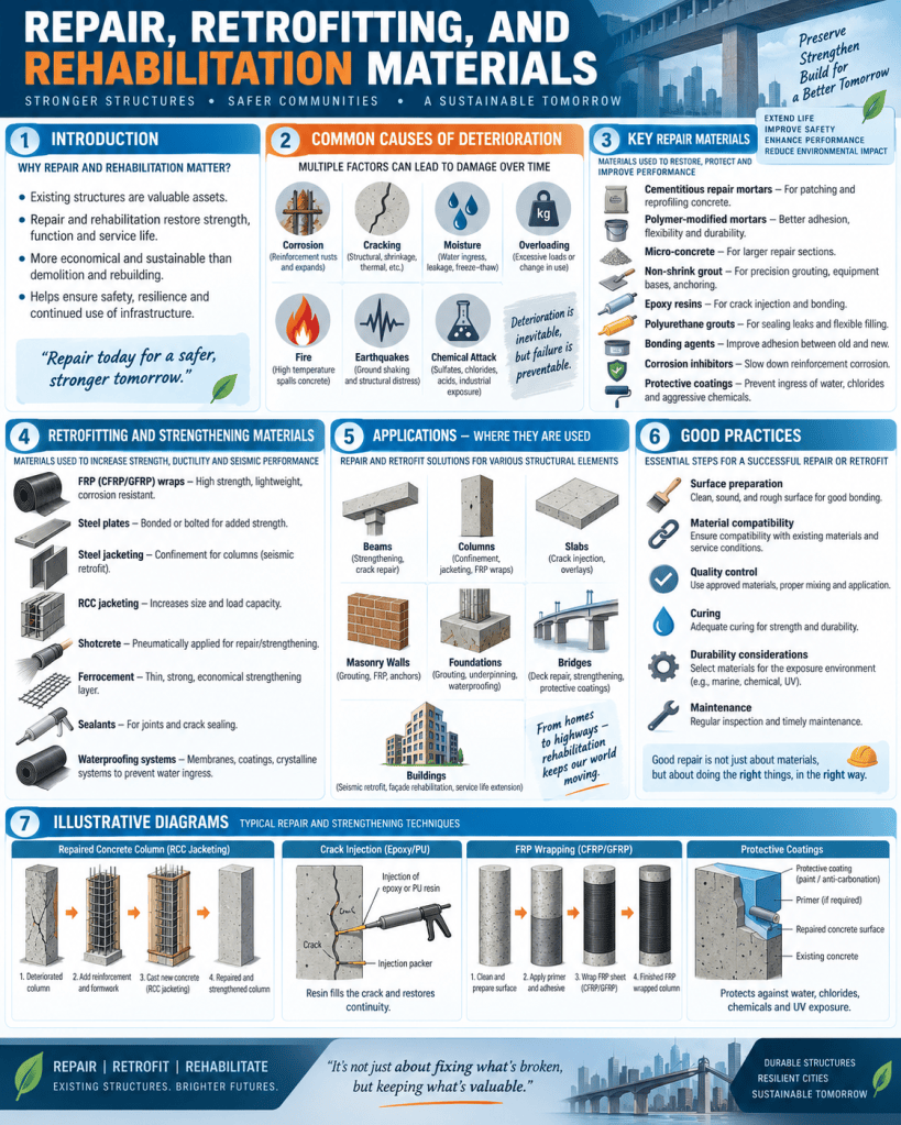
Although these three terms are closely related, they have different meanings. Repair usually focuses on correcting local defects such as cracks, spalling, leakage, or damaged concrete. Retrofitting involves strengthening an existing structure so that it can carry higher loads or perform better under hazards such as earthquakes. Rehabilitation is a broader process that restores the overall functionality, safety, durability, and serviceability of a structure.

The success of these processes depends greatly on selecting suitable materials. Modern rehabilitation work uses a wide range of cementitious, polymer-based, metallic, fiber-reinforced, and composite materials. Proper diagnosis of the defect is essential before selecting the repair system.

Objectives of Repair and Rehabilitation

The main objectives are to:

  • restore structural strength;
  • improve durability;
  • stop further deterioration;
  • protect reinforcement from corrosion;
  • seal cracks and leakage paths;
  • improve seismic performance;
  • increase load-carrying capacity;
  • extend service life;
  • improve appearance and functionality.

Repair should not simply cover visible damage. The underlying cause should first be identified and controlled.

Common Causes of Structural Deterioration

Structures may require repair because of:

  • reinforcement corrosion;
  • carbonation;
  • chloride attack;
  • chemical exposure;
  • freeze-thaw action;
  • water leakage;
  • shrinkage cracking;
  • foundation settlement;
  • overloading;
  • poor detailing;
  • fire damage;
  • earthquake damage;
  • impact damage.

Concrete structures are particularly vulnerable when moisture and aggressive chemicals reach reinforcement and initiate corrosion.

Cementitious Repair Mortars

Cementitious repair mortar is one of the most widely used materials for concrete repair. It is generally made from cement, graded sand, water, and chemical or mineral additives.

It is used for:

  • patch repairs;
  • surface restoration;
  • filling shallow defects;
  • repairing spalled concrete;
  • rebuilding damaged edges.

Advantages include:

  • compatibility with concrete;
  • ease of application;
  • relatively low cost;
  • good compressive strength.

However, shrinkage must be controlled, especially in larger repairs.

Polymer-Modified Mortars

Polymer-modified mortars contain polymers such as acrylic, styrene-butadiene, or latex.

The polymer improves:

  • adhesion;
  • flexibility;
  • water resistance;
  • tensile strength;
  • durability.

These mortars are suitable for thin repairs, overlays, façade repairs, and areas where better bonding with the existing substrate is required.

Micro-Concrete

Micro-concrete is a flowable, high-strength cementitious repair material containing small aggregates.

It is commonly used for:

  • column jacketing;
  • beam repair;
  • machine foundations;
  • congested reinforcement zones;
  • structural strengthening.

Because of its high flowability, it can fill narrow or difficult spaces without requiring heavy vibration.

Micro-concrete is especially useful when conventional concrete placement is difficult.

Non-Shrink Grout

Non-shrink grout is used where dimensional stability is important.

Common applications include:

  • base plates;
  • machine foundations;
  • precast joints;
  • anchor bolts;
  • structural gaps;
  • column bases.

The material is designed to minimize shrinkage after placement and maintain full contact between connected surfaces.

Epoxy Resin

Epoxy resins are widely used in structural repair because of their strong bonding capability.

Applications include:

  • crack injection;
  • bonding old and new concrete;
  • anchoring reinforcement;
  • surface sealing;
  • structural adhesives.

Epoxy can develop high tensile and compressive strength.

However, epoxy is generally less tolerant of wet surfaces and elevated temperatures than some cementitious systems.

Epoxy Injection

Epoxy injection is used for repairing fine structural cracks in concrete.

The procedure typically includes:

  1. cleaning the crack;
  2. sealing the surface;
  3. installing injection ports;
  4. injecting epoxy under controlled pressure;
  5. allowing the resin to cure.

This can restore continuity across cracks if the crack is dormant and the underlying cause has been addressed.

Polyurethane Resins

Polyurethane materials are especially useful for sealing cracks that experience moisture or minor movement.

Polyurethane injection may be used for:

  • water leakage;
  • basement cracks;
  • tunnels;
  • retaining walls;
  • wet joints.

Some polyurethane systems react with water and expand into a foam, helping block active leaks.

Unlike rigid epoxy, polyurethane can provide greater flexibility.

Bonding Agents

Bonding agents improve adhesion between existing and new materials.

Common types include:

  • epoxy bonding agents;
  • polymer latex;
  • cement slurry with additives.

They are used before placing repair mortar, overlays, or concrete.

Surface preparation remains essential even when bonding agents are used.

Corrosion Inhibitors

Corrosion inhibitors are materials used to slow or prevent reinforcement corrosion.

They may be:

  • mixed into repair materials;
  • applied to exposed reinforcement;
  • applied to concrete surfaces.

Their purpose is to reduce electrochemical activity and protect steel.

Corrosion inhibitors are often used together with patch repairs and protective coatings.

Rust Converters and Reinforcement Coatings

When corroded reinforcement is exposed during repair, rust must be removed and the steel cleaned.

Protective coatings may then be applied.

These coatings may be:

  • cementitious;
  • epoxy-based;
  • polymer-based.

Their role is to provide a protective barrier and improve bond with the surrounding repair material.

Protective Surface Coatings

Protective coatings are applied to concrete or masonry surfaces to reduce water and chemical penetration.

Examples include:

  • acrylic coatings;
  • epoxy coatings;
  • polyurethane coatings;
  • silane or siloxane water repellents;
  • elastomeric coatings.

These systems help reduce:

  • carbonation;
  • chloride ingress;
  • moisture penetration;
  • chemical attack.

Elastomeric coatings are useful where small surface cracks need to be bridged.

Fiber-Reinforced Polymer

Fiber-Reinforced Polymer (FRP) is an important modern strengthening material.

It consists of high-strength fibers embedded in a polymer matrix.

Common types include:

  • CFRP – Carbon Fiber-Reinforced Polymer;
  • GFRP – Glass Fiber-Reinforced Polymer;
  • AFRP – Aramid Fiber-Reinforced Polymer.

FRP can be supplied as sheets, strips, plates, bars, or wraps.

CFRP Strengthening

Carbon fiber-reinforced polymer is widely used for strengthening concrete structures.

Applications include:

  • beam flexural strengthening;
  • shear strengthening;
  • column confinement;
  • slab strengthening;
  • seismic retrofitting.

Advantages include:

  • very high strength-to-weight ratio;
  • corrosion resistance;
  • low added weight;
  • rapid installation;
  • minimal increase in member size.

Its main limitations are relatively high cost, surface preparation requirements, and sensitivity to high temperature unless protected.

GFRP

Glass fiber-reinforced polymer is generally less expensive than carbon fiber.

It offers:

  • corrosion resistance;
  • low weight;
  • good tensile strength.

GFRP is used for strengthening, reinforcement bars, façades, and other applications where extreme stiffness is not essential.

Steel Plate Bonding

Steel plates can be bonded or bolted to existing concrete members to increase capacity.

This method may be used for:

  • beams;
  • slabs;
  • columns;
  • connection regions.

Steel plate strengthening can be effective but requires corrosion protection and careful detailing.

Steel Jacketing

Steel jacketing is used to strengthen columns and sometimes beams.

Steel plates or angles are placed around the existing member and connected through bolts or welding.

Advantages include:

  • significant increase in strength;
  • improved confinement;
  • rapid installation.

Steel jacketing is especially useful where high load capacity is required.

RCC Jacketing

RCC jacketing involves increasing the size of an existing reinforced concrete member by adding:

  • new reinforcement;
  • new concrete or micro-concrete;
  • shear connectors or dowels.

It is commonly used for columns and beams.

Benefits include:

  • increased axial capacity;
  • improved flexural strength;
  • greater stiffness;
  • improved seismic resistance.

However, jacketing increases member dimensions and adds weight.

Shotcrete and Gunite

Shotcrete is concrete or mortar pneumatically projected onto a surface at high velocity.

It can be applied to:

  • walls;
  • tunnels;
  • bridges;
  • retaining structures;
  • damaged concrete surfaces.

Shotcrete provides good compaction and bond.

It is useful for repairing large irregular surfaces and for seismic strengthening.

Gunite generally refers to a dry-mix sprayed mortar process, while shotcrete may include wet-mix systems.

Ferrocement

Ferrocement consists of a thin cement mortar matrix reinforced with closely spaced layers of wire mesh.

It is used for:

  • thin jackets;
  • walls;
  • tanks;
  • shells;
  • repair overlays.

Advantages include good crack control, lightweight construction, and ease of forming around complex shapes.

Grouting Materials

Grouting is used to fill voids, cracks, joints, or spaces in soil and structures.

Common grouting materials include:

  • cement grout;
  • chemical grout;
  • epoxy grout;
  • polyurethane grout.

Applications include:

  • foundation strengthening;
  • void filling;
  • masonry consolidation;
  • crack sealing;
  • soil improvement.

Crack-Filling Materials

Not all cracks require structural epoxy.

Different materials are selected according to crack type.

Common options include:

  • epoxy for structural dormant cracks;
  • polyurethane for leaking cracks;
  • polymer sealants for movement joints;
  • cement slurry for larger non-critical cracks;
  • flexible sealants for dynamic cracks.

Correct crack diagnosis is essential.

Sealants

Sealants are flexible materials used at joints and cracks where movement is expected.

Common types include:

  • silicone;
  • polyurethane;
  • polysulfide;
  • acrylic.

They are used around:

  • façades;
  • windows;
  • expansion joints;
  • concrete joints;
  • roofing systems.

Sealants must remain flexible and maintain adhesion.

Waterproofing Materials

Waterproofing is often an important part of rehabilitation.

Common systems include:

  • cementitious coatings;
  • bituminous membranes;
  • liquid-applied polyurethane;
  • acrylic coatings;
  • sheet membranes;
  • crystalline waterproofing.

Waterproofing prevents future deterioration caused by moisture.

Crystalline Waterproofing

Crystalline waterproofing contains chemicals that react with moisture and cement compounds to form insoluble crystals within concrete pores.

It is used for:

  • basements;
  • tanks;
  • tunnels;
  • foundations.

The crystals reduce water permeability.

Repair of Masonry Structures

Masonry rehabilitation may use:

  • lime mortar;
  • compatible cement-lime mortar;
  • grout injection;
  • stainless steel ties;
  • crack stitching bars;
  • stone replacement.

Historic masonry requires special care because overly strong repair materials can damage original bricks or stone.

Compatibility is more important than simply achieving maximum strength.

Crack Stitching

Crack stitching involves inserting metal bars across cracks.

Slots are cut across the crack, and bars are fixed with grout or resin.

This helps reconnect separated masonry and distribute tensile stresses.

Underpinning Materials

Foundation rehabilitation may require underpinning.

Materials include:

  • concrete;
  • reinforced concrete;
  • structural steel;
  • micropiles;
  • grout.

Micropiles are especially useful where access is restricted or stronger soil lies at greater depth.

Seismic Retrofitting Materials

Earthquake retrofitting aims to improve strength, stiffness, and ductility.

Common materials and systems include:

  • FRP wraps;
  • steel bracing;
  • RCC jackets;
  • steel jackets;
  • shotcrete;
  • shear walls;
  • dampers;
  • base isolation devices.

Material selection depends on the existing structure and expected seismic demand.

Steel Bracing

Steel bracing can improve the lateral resistance of framed buildings.

Common systems include:

  • X-bracing;
  • V-bracing;
  • inverted V-bracing.

Bracing can often be installed with relatively limited disturbance compared with adding large concrete walls.

Addition of Shear Walls

Reinforced concrete shear walls may be added during rehabilitation to increase lateral stiffness.

They are particularly effective in buildings with weak resistance to wind or earthquake forces.

However, foundation strengthening may also be required to support the additional loads.

Repair of Fire-Damaged Structures

After fire exposure, concrete, steel, and masonry should be carefully assessed.

Repair may include:

  • removal of weakened concrete;
  • reinforcement replacement;
  • protective coatings;
  • section rebuilding;
  • FRP strengthening;
  • steel plate strengthening.

Fire-damaged materials should not be covered until their residual strength has been evaluated.

Surface Preparation

Surface preparation is one of the most important steps in repair work.

Before repair materials are applied, surfaces may need:

  • removal of loose concrete;
  • cleaning;
  • roughening;
  • dust removal;
  • reinforcement cleaning;
  • moisture conditioning.

Poor surface preparation can cause repair failure even when high-quality materials are used.

Compatibility of Repair Materials

Repair materials should be compatible with the existing substrate.

Important properties include:

  • strength;
  • modulus of elasticity;
  • shrinkage;
  • thermal expansion;
  • permeability;
  • bond strength.

A repair material that is much stronger or stiffer than the original material can sometimes create stress concentrations.

Durability Considerations

A successful repair should address the long-term environment.

For example, repairing corrosion damage without stopping chloride or water ingress may only provide temporary improvement.

Durable repair therefore combines:

  • defect removal;
  • structural restoration;
  • corrosion protection;
  • waterproofing;
  • protective coatings;
  • proper drainage.

Quality Control

Repair and retrofitting work requires careful inspection.

Important checks include:

  • substrate preparation;
  • crack condition;
  • reinforcement cleaning;
  • material mixing;
  • application thickness;
  • curing;
  • bond quality;
  • anchor installation.

Specialized strengthening systems such as FRP should be installed according to approved procedures.

Non-Destructive Testing

Before and after rehabilitation, non-destructive tests may be used.

Examples include:

  • rebound hammer testing;
  • ultrasonic pulse velocity;
  • cover meter surveys;
  • half-cell potential;
  • infrared thermography.

These methods help assess condition without extensive damage to the structure.

Sustainability Benefits

Repair and rehabilitation can be more sustainable than demolition and reconstruction.

Benefits include:

  • conservation of existing materials;
  • reduction in demolition waste;
  • lower demand for new resources;
  • lower embodied energy;
  • extension of building life.

Retrofitting also allows existing buildings to meet new functional, structural, or energy requirements.

Selecting the Right Repair Material

Selection should consider:

  • cause of damage;
  • structural importance;
  • exposure conditions;
  • crack movement;
  • moisture;
  • required strength;
  • access;
  • cost;
  • durability.

There is no single material suitable for all repairs.

For example, epoxy may be ideal for a dry structural crack, while polyurethane may be more appropriate for a leaking moving crack.

Maintenance After Rehabilitation

Repaired structures should continue to be monitored.

Periodic inspections should check for:

  • new cracks;
  • coating deterioration;
  • water leakage;
  • corrosion;
  • movement;
  • joint failure.

Early maintenance helps protect the investment made in rehabilitation.

Conclusion

Repair, retrofitting, and rehabilitation materials play a vital role in extending the service life of buildings and infrastructure. Materials such as cementitious repair mortars, polymer-modified mortars, micro-concrete, epoxy resins, polyurethane, FRP composites, steel plates, shotcrete, sealants, waterproofing systems, and protective coatings provide a wide range of solutions for structural and durability problems.
The choice of material should always follow a proper investigation of the damage. Repair treats defects, retrofitting improves structural capacity, and rehabilitation restores the overall performance and usability of a structure.

The most effective rehabilitation does not merely hide visible damage. It addresses the underlying cause, restores structural behavior, protects the repaired area from future deterioration, and ensures compatibility between old and new materials.

When supported by good diagnosis, proper surface preparation, skilled application, quality control, and continued maintenance, modern repair and retrofitting materials can significantly improve the safety, durability, resilience, and sustainability of existing structures.

Daily writing prompt
How do you write what people actually want to read?

Principles of Modular Coordination and Dimensional Grids

Introduction

Modular coordination and dimensional grids are fundamental concepts in architecture, building construction, industrialized building systems, and interior planning. They help bring order, consistency, efficiency, and economy to the design and construction process. In simple terms, modular coordination means planning building dimensions and components according to a basic module or standard unit of measurement, while dimensional grids refer to the organized system of reference lines used to position structural and architectural elements accurately within a plan.

These principles are especially important in modern construction because buildings are no longer made only through completely individual, handcrafted methods. Instead, many building elements such as doors, windows, wall panels, tiles, furniture systems, structural members, and prefabricated components are manufactured in standard sizes. If building dimensions are coordinated with these standard modules, materials can fit more easily, waste can be reduced, and construction becomes faster and more economical.

Thus, modular coordination and dimensional grids are not just drafting tools; they are planning principles that connect design, production, construction, and maintenance into a more rational system.

Meaning of Modular Coordination

Modular coordination is the use of a standard module as the basis for setting out dimensions of buildings, spaces, and building components. The module acts as a common dimensional reference so that different elements can fit together properly.

A module is a basic unit of size adopted for coordination. In building practice, a common basic module may be 100 mm or another agreed unit depending on the system used. Dimensions of rooms, wall panels, columns, openings, doors, windows, tiles, furniture layouts, and structural spacing can then be planned as multiples or submultiples of this module.

For example, if 100 mm is taken as the basic module, then dimensions such as 300 mm, 600 mm, 1200 mm, 2400 mm, and 3600 mm are all modular dimensions. This creates compatibility between different building parts.

Objectives of Modular Coordination

The main objectives of modular coordination are to:

  • standardize dimensions;
  • improve compatibility of building components;
  • reduce cutting and wastage;
  • simplify design and detailing;
  • improve speed of construction;
  • support prefabrication and industrialization;
  • reduce cost;
  • facilitate maintenance and replacement;
  • improve dimensional accuracy.

A modular approach is particularly beneficial where building components are produced in factories and assembled on site.

Basic Principles of Modular Coordination

Several principles guide modular coordination in building design.

1. Use of a Standard Basic Module

The first principle is to adopt a standard module that becomes the common dimensional basis for planning. Once the module is selected, all major dimensions should relate to it wherever practical.

This does not mean every dimension must be identical, but it means dimensions should be coordinated in modular increments.

2. Coordination of Building Components

All building components should be dimensionally related so that they fit together without excessive adjustment.

These components may include:

  • structural bays;
  • wall thicknesses;
  • door and window openings;
  • stair dimensions;
  • flooring units;
  • ceiling panels;
  • service ducts;
  • furniture modules.

The success of modular design depends on the ability of different components to connect logically.

3. Dimensional Compatibility

A building should be designed so that components from different manufacturers or systems can be assembled within the same dimensional logic. This reduces the need for custom fabrication and site modification.

Dimensional compatibility is especially important in prefabricated construction and open building systems.

4. Rational Space Planning

Spaces such as rooms, corridors, kitchens, classrooms, and offices should be dimensioned according to modular principles so that furniture, fixtures, and circulation can be arranged efficiently.

This improves both function and economy.

5. Reduction of Waste

When wall lengths, floor sizes, ceiling layouts, and surface finishes are planned using modular increments, fewer materials need to be cut. This reduces:

  • material wastage;
  • labor time;
  • construction debris;
  • cost.

6. Ease of Repetition

Modular coordination encourages repeated use of the same dimensions and details. Repetition simplifies construction and improves productivity.

This is particularly useful in:

  • housing projects;
  • office buildings;
  • schools;
  • hospitals;
  • hotels;
  • industrial buildings.

Modular Dimensions in Building Design

Modular coordination may be applied at several scales.

Component Level

At the smallest level, individual components such as bricks, blocks, tiles, doors, and windows can be dimensioned in modular units.

Assembly Level

Groups of components, such as wall panels, façade systems, partitions, and furniture systems, can also be based on modules.

Building Level

At the overall building level, modular coordination can influence:

  • room sizes;
  • bay spacing;
  • floor-to-floor height;
  • façade rhythm;
  • planning grids.

Thus, modular thinking extends from the smallest unit to the entire building.

Horizontal and Vertical Coordination

Modular coordination must work in both horizontal and vertical directions.

Horizontal Coordination

This concerns dimensions in plan, such as:

  • room length and width;
  • wall spacing;
  • column spacing;
  • corridor widths;
  • location of openings.

Vertical Coordination

This concerns heights and levels, such as:

  • floor-to-floor heights;
  • sill levels;
  • lintel heights;
  • door heights;
  • ceiling levels;
  • structural depths.

Both directions must be coordinated so that all components align properly.

Dimensional Grids

A dimensional grid is a system of horizontal and vertical reference lines used to organize the placement of structural and architectural elements.

In building drawings, grids are usually represented by evenly spaced lines identified by numbers and letters. For example, one direction may be labeled 1, 2, 3, 4, while the other may be labeled A, B, C, D.

The intersections of these lines become reference points for locating:

  • columns;
  • walls;
  • beams;
  • partition lines;
  • service cores;
  • façade elements.

The grid acts as a framework for accurate planning and construction.

Purpose of Dimensional Grids

Dimensional grids are used to:

  • organize the building layout;
  • establish positional control;
  • coordinate structural and architectural drawings;
  • simplify communication between consultants;
  • assist in setting out on site;
  • ensure alignment and consistency.

Without a clear grid system, the design and construction process can become confusing and prone to dimensional errors.

Types of Grids

Different types of dimensional grids may be used depending on the project.

Structural Grid

A structural grid is based primarily on the placement of columns, load-bearing walls, beams, and structural bays.

This is especially important in framed structures such as RCC and steel buildings.

Planning Grid

A planning grid is used more broadly for spatial organization and may guide room sizes, partition layouts, and façade modules.

Service Grid

In some projects, service systems such as ceiling layouts, lighting, HVAC diffusers, and raised floors may follow their own modular grid while still coordinating with the main structural grid.

Principles of Dimensional Grids

1. Clarity

The grid should be simple and easy to understand. Unnecessarily complicated grids create confusion in design and execution.

2. Consistency

Grid spacing should follow a consistent logic. Regular spacing improves planning efficiency and structural simplicity.

3. Functional Suitability

The grid should suit the intended building use. For example, an office building may need a different grid spacing from a hospital, classroom building, or industrial shed.

4. Structural Efficiency

Grid spacing should allow efficient structural design. Very small spacing may increase the number of columns unnecessarily, while very large spacing may make beams and slabs uneconomical.

5. Coordination with Building Components

The grid should relate to modular sizes of walls, openings, ceiling panels, partitions, and furniture systems.

6. Flexibility

A well-designed grid should allow future changes in space layout or service arrangement.

Advantages of Modular Coordination and Grids

The use of modular coordination and dimensional grids offers many benefits.

Improved Design Efficiency

Designers can make decisions more quickly because dimensions follow a rational system.

Better Construction Accuracy

Grid lines provide clear references during setting out, reducing mistakes on site.

Faster Construction

Standardized dimensions and repeated components speed up fabrication and assembly.

Support for Prefabrication

Prefabricated panels, structural systems, and interior components work more effectively when coordinated by modules and grids.

Easier Interdisciplinary Coordination

Architects, structural engineers, and service consultants can all refer to the same grid system.

Reduced Cost

Standardization, repetition, and reduced waste contribute to economy.

Better Maintenance and Replacement

Modular components are easier to replace or upgrade because their dimensions are standardized.

Applications in Modern Construction

These principles are widely used in contemporary construction.

Residential Buildings

Modular room sizes, kitchen layouts, toilet units, and structural bays improve economy and repetition in housing.

Office Buildings

Open-plan offices benefit greatly from dimensional grids because workstations, partitions, lighting, and services can be arranged more flexibly.

Industrial Buildings

Factories and warehouses often use large structural grids to accommodate machinery, circulation, and modular roofing systems.

Schools and Hospitals

Repetitive rooms such as classrooms, wards, and consultation rooms can be planned using modular logic.

Interior Systems

False ceilings, raised access floors, partition systems, storage units, and façade cladding often depend on modular dimensions.

Relationship with Prefabrication

Modular coordination is closely related to prefabrication.

In prefabricated construction, components are manufactured in standard sizes before arriving on site. If the building design does not follow modular principles, these components may not fit properly, causing delays and costly modifications.

Thus, modular coordination is one of the essential foundations of industrialized building systems.

Challenges in Modular Coordination

Despite its advantages, modular design also presents some challenges.

  • It may be seen as restrictive if applied too rigidly.
  • Irregular sites may require adjustments.
  • Complex forms may not fit easily within regular modules.
  • Coordination among many disciplines is required.
  • Tolerances must be managed carefully.

However, these challenges can usually be addressed through thoughtful planning rather than abandoning the modular approach.

Modular Coordination and Human Use

Modular planning should not be based only on construction efficiency. It must also respond to human needs.

Spaces must remain comfortable, functional, and proportionate. Good modular design therefore balances:

  • structural logic;
  • manufacturing efficiency;
  • human scale;
  • spatial quality;
  • aesthetics.

A grid should support architecture, not destroy creativity.

Conclusion

Principles of modular coordination and dimensional grids play a vital role in rational building design and construction. Modular coordination ensures that spaces, components, and systems relate to a standard dimensional unit, while dimensional grids provide the reference framework for setting out and organizing the building accurately.

Together, they improve compatibility, reduce waste, support prefabrication, simplify construction, and enhance interdisciplinary coordination. They also make buildings more economical, adaptable, and easier to maintain.

In an age of increasing standardization, prefabrication, and complex building services, these principles are more important than ever. When used intelligently, modular coordination and dimensional grids help create buildings that are not only efficient to build but also functional, orderly, and flexible in use.

If you want, I can also make a poster for “Principles of Modular Coordination and Dimensional Grids”.

Principles of Modular Coordination and Dimensional Grids

Daily writing prompt
How do you write what people actually want to read?

Flooring Systems: Tiles, Terrazzo, Concrete, and Raised Access Floors

Introduction

Flooring is one of the most important finishing elements in a building because it directly affects durability, comfort, appearance, maintenance, safety, acoustics, and overall user experience. A good flooring system should be selected according to the function of the space, expected traffic, moisture conditions, structural requirements, maintenance needs, and budget. Different buildings require different flooring solutions. For example, residential spaces may prioritize comfort and appearance, while commercial, industrial, institutional, and data-processing spaces may require high durability, easy cleaning, or flexible access to services.

Among the widely used flooring systems are tile flooring, terrazzo flooring, concrete flooring, and raised access floors. Each system has its own construction method, materials, benefits, limitations, and applications. Understanding these flooring systems helps architects, engineers, contractors, and students make appropriate decisions for different types of buildings.

Functions of Flooring

Flooring performs several functions beyond simply providing a walking surface.

A good floor should:

  • provide a level and durable surface;
  • resist wear and impact;
  • support furniture and equipment;
  • contribute to thermal and acoustic comfort;
  • provide slip resistance;
  • resist moisture where required;
  • allow easy cleaning and maintenance;
  • improve the aesthetic quality of interiors.

The performance of flooring depends not only on the surface material but also on the quality of the base, subfloor, screed, joints, adhesives, and workmanship.

Basic Components of a Flooring System

A typical flooring system may consist of several layers.

These may include:

  • structural slab;
  • damp-proof or waterproof layer;
  • leveling screed;
  • adhesive or bedding mortar;
  • flooring finish;
  • joint filler or sealant.

In some applications, additional layers may include insulation, acoustic mats, vapor barriers, or underfloor services.

Proper preparation of the substrate is essential because unevenness, cracks, moisture, or contamination can lead to later flooring failure.

Tile Flooring

Tile flooring is one of the most widely used systems in residential, commercial, institutional, and public buildings. Tiles are available in a wide variety of materials, sizes, finishes, colors, and textures.

Common tile materials include:

  • ceramic tiles;
  • porcelain tiles;
  • vitrified tiles;
  • natural stone tiles;
  • cement tiles;
  • mosaic tiles.

Ceramic Tiles

Ceramic tiles are produced from clay and other minerals that are shaped and fired at high temperature.

They may be glazed or unglazed.

Advantages include:

  • wide design range;
  • ease of cleaning;
  • water resistance;
  • relatively low maintenance;
  • suitability for walls and floors.

Ceramic tiles are commonly used in kitchens, bathrooms, residential rooms, and commercial interiors.

Porcelain Tiles

Porcelain tiles are denser and less porous than many conventional ceramic tiles.

They offer:

  • high strength;
  • good stain resistance;
  • low water absorption;
  • durability;
  • suitability for high-traffic areas.

Porcelain tiles may imitate stone, timber, concrete, or other materials.

Vitrified Tiles

Vitrified tiles are manufactured through a process that produces a dense and glass-like body.

They are popular because of their:

  • low porosity;
  • smooth finish;
  • durability;
  • resistance to stains;
  • consistent dimensions.

They are widely used in modern residential and commercial interiors.

Tile Installation

Tiles may be fixed using:

  • cement-sand mortar;
  • tile adhesive;
  • specialized thin-set systems.

The substrate should be clean, stable, and level.

Important installation steps include:

  1. checking the base;
  2. setting out the tile pattern;
  3. applying adhesive;
  4. placing tiles with correct spacing;
  5. checking alignment and level;
  6. grouting joints;
  7. cleaning the finished surface.

Proper joint width is important to accommodate dimensional variation and minor movement.

Advantages of Tile Flooring

Tile flooring offers several benefits:

  • wide range of designs;
  • good moisture resistance;
  • easy maintenance;
  • durability;
  • compatibility with underfloor heating;
  • resistance to stains and chemicals in many cases.

However, some tiles may be slippery when wet.

Therefore, slip-resistant finishes should be selected for bathrooms, ramps, external areas, and other wet locations.

Terrazzo Flooring

Terrazzo is a composite flooring material made by combining decorative aggregates with a cementitious or resin-based binder.

Aggregates may include:

  • marble chips;
  • granite chips;
  • quartz;
  • glass;
  • recycled materials.

After placement, the surface is ground and polished to create a smooth and decorative finish.

Terrazzo has been used for centuries and remains popular in public and institutional buildings because of its durability.

Types of Terrazzo

Cement-Based Terrazzo

This traditional system uses cement as the binder.

It is usually thicker and heavier than resin-based terrazzo.

Epoxy Terrazzo

Epoxy terrazzo uses a resin binder.

It allows thinner construction and a wider range of colors.

It also provides a smooth and highly decorative surface.

Construction of Terrazzo Flooring

The typical process includes:

  1. preparing the concrete base;
  2. installing divider strips;
  3. placing the terrazzo mixture;
  4. compacting and leveling;
  5. allowing the surface to cure;
  6. grinding;
  7. filling small voids;
  8. polishing;
  9. sealing where required.

Divider strips are commonly made from brass, aluminum, zinc, or other materials.

They help control cracking and create patterns.

Advantages of Terrazzo

Terrazzo offers:

  • long service life;
  • excellent wear resistance;
  • seamless appearance;
  • high decorative potential;
  • low maintenance;
  • suitability for high traffic.

It is commonly used in:

  • airports;
  • hospitals;
  • educational buildings;
  • shopping centers;
  • public halls;
  • institutional buildings.

A well-maintained terrazzo floor can remain functional for many decades.

Limitations of Terrazzo

Potential limitations include:

  • higher initial cost;
  • skilled workmanship requirements;
  • longer installation time for some systems;
  • risk of cracking if the substrate moves;
  • hard walking surface.

Proper movement joints and substrate design are therefore important.

Concrete Flooring

Concrete flooring is commonly used in industrial, commercial, institutional, and modern architectural interiors.

A concrete floor may be left as a simple finished slab or treated with decorative and protective systems.

Concrete floors can be:

  • power-trowelled;
  • polished;
  • stained;
  • colored;
  • textured;
  • coated.

Basic Concrete Floor Construction

Concrete flooring usually involves placing concrete over a prepared base or structural slab.

The sequence may include:

  1. subgrade preparation;
  2. granular base;
  3. vapor barrier where required;
  4. reinforcement;
  5. concrete placement;
  6. compaction;
  7. screeding;
  8. finishing;
  9. joint formation;
  10. curing.

Good curing is essential for strength and durability.

Polished Concrete

Polished concrete is produced by mechanically grinding and polishing the concrete surface.

The process may involve progressively finer abrasives.

A densifier may also be applied to harden the surface.

Advantages include:

  • high durability;
  • modern appearance;
  • easy cleaning;
  • reduced need for additional floor finishes;
  • long service life.

Polished concrete is commonly used in offices, shops, airports, warehouses, and contemporary residences.

Industrial Concrete Floors

Industrial floors are designed for heavy traffic and equipment loads.

They may be used in:

  • factories;
  • warehouses;
  • logistics centers;
  • workshops;
  • parking facilities.

These floors must often resist:

  • forklifts;
  • impact;
  • abrasion;
  • chemicals;
  • heavy machinery.

Special surface hardeners or coatings may be used to improve performance.

Concrete Floor Joints

Concrete shrinks and expands due to temperature and moisture changes.

Joints are therefore essential.

Common types include:

  • construction joints;
  • contraction joints;
  • isolation joints;
  • expansion joints.

Poor joint design can lead to uncontrolled cracking.

Advantages of Concrete Flooring

Concrete flooring offers:

  • high compressive strength;
  • durability;
  • resistance to heavy loads;
  • relatively low maintenance;
  • thermal mass;
  • compatibility with industrial use.

However, concrete can feel hard and cold underfoot and may develop cracks if not correctly designed and cured.

Raised Access Floors

Raised access flooring is a specialized system in which floor panels are elevated above the structural floor slab, creating a concealed service zone underneath.

The system is particularly useful in buildings that require frequent access to electrical, communication, data, or mechanical services.

A typical raised access floor consists of:

  • pedestal supports;
  • stringers where required;
  • removable floor panels;
  • finished surface covering.

Pedestal System

Pedestals are vertical adjustable supports fixed to the structural slab.

They allow the floor height to be accurately controlled.

The void beneath the panels can accommodate:

  • cables;
  • data lines;
  • electrical systems;
  • air distribution;
  • pipes.

Floor Panels

Panels may be manufactured from:

  • steel;
  • calcium sulfate;
  • wood-core materials;
  • cementitious materials;
  • composite systems.

The top surface may receive:

  • carpet tiles;
  • vinyl;
  • laminate;
  • stone;
  • antistatic finishes.

Panels are usually removable, allowing easy access to services below.

Applications of Raised Access Floors

Raised floors are commonly used in:

  • data centers;
  • server rooms;
  • offices;
  • control rooms;
  • trading floors;
  • laboratories;
  • telecommunications facilities.

They are particularly valuable where technical services change frequently.

Advantages of Raised Access Floors

The system provides several benefits:

  • easy access to services;
  • flexible office layouts;
  • simplified cable management;
  • quick maintenance;
  • adaptable electrical distribution;
  • potential use for underfloor air conditioning.

Raised floors can significantly reduce disruption when office workstations or technology systems are relocated.

Limitations of Raised Floors

Potential disadvantages include:

  • higher initial cost;
  • reduction in clear room height;
  • need for careful structural design;
  • vibration concerns;
  • requirement for precise installation;
  • need for fire stopping around penetrations.

In areas with heavy equipment, panel load capacity must be carefully checked.

Comparison of Flooring Systems

Each flooring system serves a different purpose.

Tiles are ideal where easy maintenance, moisture resistance, and visual variety are important.

Terrazzo is suitable for prestigious, high-traffic environments requiring durability and decorative quality.

Concrete flooring is appropriate for industrial, commercial, and minimalist architectural applications.

Raised access flooring is best suited to technology-intensive spaces requiring flexible access to services.

Selection should be based on:

  • traffic level;
  • moisture exposure;
  • maintenance;
  • structural load;
  • appearance;
  • cost;
  • service requirements.

Flooring and Moisture Control

Moisture is a major cause of flooring failure.

Problems may include:

  • tile debonding;
  • staining;
  • adhesive failure;
  • mold growth;
  • terrazzo discoloration;
  • coating blistering.

Moisture barriers should be used where required, especially over ground-bearing slabs.

The concrete substrate should also have adequate moisture conditions before sensitive flooring is installed.

Slip Resistance

Safety is an important flooring consideration.

Wet areas require surfaces with adequate slip resistance.

Such areas include:

  • bathrooms;
  • kitchens;
  • entrances;
  • swimming pool decks;
  • ramps;
  • external walkways.

Highly polished surfaces should be used carefully in locations exposed to water.

Acoustic Performance

Hard floor finishes can reflect sound and increase noise.

Acoustic performance can be improved through:

  • resilient underlays;
  • acoustic mats;
  • carpet finishes;
  • floating floors;
  • insulated raised floors.

Acoustic requirements are particularly important in apartments, offices, schools, and hospitals.

Thermal Comfort

Floor materials influence thermal sensation.

Tiles, terrazzo, and concrete may feel cool, which can be useful in hot climates.

These materials also work effectively with radiant or underfloor heating systems because of their thermal mass.

Raised floors can also support underfloor air-distribution systems.

Maintenance

Different flooring systems require different maintenance strategies.

Tile floors generally require regular cleaning and periodic grout maintenance.

Terrazzo may require polishing and resealing.

Concrete floors may require re-polishing or repair of joints.

Raised floors require inspection of:

  • panels;
  • pedestals;
  • service voids;
  • edge details.

Preventive maintenance extends the service life of flooring.

Sustainability

Flooring can contribute to sustainable building design.

Considerations include:

  • locally sourced materials;
  • recycled content;
  • long service life;
  • low-maintenance finishes;
  • reduced replacement frequency;
  • low-emission adhesives;
  • reuse and recyclability.

Terrazzo can incorporate recycled aggregates, while concrete can use supplementary cementitious materials. Raised floor systems may also allow building services to be changed without major demolition.

Common Flooring Defects

Typical defects include:

  • cracks;
  • uneven surfaces;
  • hollow tiles;
  • loose tiles;
  • stained grout;
  • terrazzo cracking;
  • concrete dusting;
  • panel rocking in raised floors;
  • damaged finishes.

Many defects result from poor substrate preparation, inadequate joints, moisture, or improper installation.

Quality Control

Flooring work should be inspected for:

  • level and flatness;
  • joint alignment;
  • adhesion;
  • surface finish;
  • moisture condition;
  • slope in wet areas;
  • edge detailing.

Raised flooring should additionally be checked for pedestal alignment, panel stability, and load capacity.

Conclusion

Flooring systems play an important role in the performance, appearance, and functionality of buildings. Tile flooring provides versatility, moisture resistance, and ease of maintenance. Terrazzo offers exceptional durability and decorative quality. Concrete flooring provides strength, economy, and suitability for heavy-duty applications, while raised access floors provide flexibility and easy access to technical services.

The successful performance of any flooring system depends on proper substrate preparation, material selection, joint design, moisture control, installation, and maintenance. Floors must also address safety, thermal comfort, acoustics, and expected loading.

When the right flooring system is selected for the intended use, it can provide a durable, attractive, safe, and efficient surface that contributes significantly to the long-term quality of the built environment.

Daily writing prompt
How do you write what people actually want to read?

Fire Protection Materials, Fire Rating, and Compartmentation

Introduction

Fire safety is a fundamental part of building design and construction. A building must not only provide shelter and functional space but also protect occupants and structural systems during a fire. Effective fire protection depends on a combination of fire-resistant materials, appropriate fire ratings, compartmentation, detection systems, evacuation planning, and firefighting provisions.

Among these measures, passive fire protection is especially important because it is built into the structure itself. Passive fire protection includes fire-resistant walls, floors, doors, ceilings, structural coatings, and compartment barriers that limit the spread of flames, heat, and smoke. Unlike active systems such as sprinklers or alarms, passive systems do not require activation to perform their basic role.

Understanding fire protection materials, fire ratings, and compartmentation is essential for architects, civil engineers, building designers, facility managers, and construction professionals.

Fire Behaviour in Buildings

A fire requires three basic elements:

  • fuel;
  • oxygen;
  • heat.

Together, these are often described as the fire triangle.

In a building, fuel may include furniture, finishes, timber, plastics, fabrics, papers, and stored materials. Once ignition occurs, heat can spread through radiation, convection, and conduction.

The severity of a building fire depends on:

  • quantity and type of combustible material;
  • ventilation;
  • room size;
  • surface finishes;
  • structural materials;
  • fire protection systems.

The main objective of fire-resistant construction is to delay structural failure and restrict fire and smoke movement long enough for occupants to escape and firefighters to respond.

Passive and Active Fire Protection

Fire safety systems can broadly be divided into passive and active protection.

Passive Fire Protection

Passive systems are built into the structure.

Examples include:

  • fire-resistant walls;
  • fire-rated doors;
  • fire-resistant floors;
  • protected structural steel;
  • fire stops;
  • smoke barriers;
  • compartment walls;
  • fire-resistant glazing.

Active Fire Protection

Active systems operate when a fire occurs.

Examples include:

  • automatic sprinklers;
  • fire alarms;
  • smoke detectors;
  • hydrants;
  • fire extinguishers;
  • smoke extraction systems.

Both systems should work together as part of an integrated fire safety strategy.

Fire Protection Materials

Different materials behave differently under fire exposure. Some materials are naturally non-combustible, while others require protective treatment.

Concrete

Concrete is generally considered to have good fire resistance because it is non-combustible and has relatively low thermal conductivity.

Advantages include:

  • does not burn;
  • delays heat transfer;
  • protects embedded reinforcement;
  • maintains structural capacity for a period during fire.

However, very high temperatures can cause cracking, spalling, and loss of strength.

Adequate concrete cover over reinforcement is therefore important for fire resistance.

Brick and Masonry

Brick, concrete block, and stone masonry generally provide good fire resistance.

Masonry walls can act as effective fire barriers when they have:

  • sufficient thickness;
  • proper mortar joints;
  • sealed penetrations;
  • suitable structural stability.

Masonry is commonly used for fire compartment walls, stair enclosures, and service shafts.

Gypsum Board

Gypsum board is widely used in fire-rated partitions and ceilings.

Gypsum contains chemically combined water. During fire exposure, this water is gradually released as vapor, helping to delay temperature rise.

Fire-resistant gypsum systems may consist of:

  • multiple board layers;
  • steel studs;
  • cavity insulation;
  • fire-resistant sealants.

The fire rating depends on the complete tested wall or ceiling assembly.

Mineral Wool

Mineral wool is a non-combustible insulation material made from mineral fibers.

It is commonly used for:

  • fire barriers;
  • wall cavities;
  • ceilings;
  • façade systems;
  • service penetrations.

It provides both thermal insulation and fire resistance.

Mineral wool is especially useful for filling gaps around pipes, ducts, and structural elements.

Calcium Silicate Boards

Calcium silicate boards are used for fire protection in walls, ceilings, shafts, and structural encasements.

Their advantages include:

  • non-combustibility;
  • good thermal resistance;
  • dimensional stability;
  • relatively low weight.

They are commonly used for protecting steel columns and beams.

Vermiculite and Perlite

Vermiculite and perlite are lightweight mineral materials that can be incorporated into plasters or boards.

They help improve thermal and fire resistance.

They are often used in:

  • sprayed fireproofing;
  • lightweight plaster;
  • fire-resistant panels;
  • steel protection systems.

Intumescent Coatings

Intumescent paint is a special coating applied to structural steel.

When exposed to high temperatures, the coating expands and forms a thick insulating char layer.

This slows the rate at which steel heats up.

Advantages include:

  • relatively thin protective layer;
  • clean architectural appearance;
  • useful for exposed steelwork;
  • adaptable to complex shapes.

Intumescent systems must be applied to the required thickness and maintained properly.

Spray-Applied Fire-Resistive Materials

Spray-applied materials are commonly used to protect steel beams and columns.

They may contain:

  • mineral fibers;
  • cementitious materials;
  • vermiculite.

The coating insulates structural steel and delays temperature rise.

Careful application is necessary to maintain uniform thickness and adhesion.

Fire-Resistant Glass

Conventional glass can crack quickly when exposed to fire.

Fire-resistant glazing is specially designed to provide a defined level of performance.

Different products may provide:

  • integrity against flames;
  • smoke control;
  • reduced heat radiation;
  • thermal insulation.

Fire-resistant glazing is used in corridors, doors, partitions, and protected escape routes.

Fire-Resistant Doors

Fire doors are critical elements in compartmentation.

They are designed to remain closed during a fire and restrict the spread of flames and smoke.

A typical fire door assembly may include:

  • fire-resistant door leaf;
  • rated frame;
  • self-closing device;
  • intumescent seals;
  • smoke seals;
  • tested ironmongery.

A fire door must be installed as a complete tested system.

Timber and Fire Protection

Timber is combustible, but its fire performance depends on size and detailing.

Large timber sections develop a char layer on their exposed surface. This char can slow further burning and protect the inner section.

Timber fire protection methods include:

  • gypsum board encasement;
  • fire-retardant treatment;
  • increased member dimensions;
  • protected connections;
  • sprinklers.

Mass timber buildings require careful fire engineering.

Steel and Fire

Steel is non-combustible but loses strength and stiffness as temperature increases.

At sufficiently high temperatures, an unprotected steel member may deform or buckle.

Steel protection methods include:

  • intumescent coatings;
  • spray-applied fireproofing;
  • concrete encasement;
  • gypsum board protection;
  • fire-resistant ceiling systems.

Fire Rating

A fire rating indicates how long a building element can maintain specified performance when exposed to a standard fire test.

Fire resistance is commonly expressed in minutes or hours, such as:

  • 30 minutes;
  • 60 minutes;
  • 90 minutes;
  • 120 minutes;
  • 180 minutes.

The required rating depends on factors such as building height, occupancy, compartment size, structural function, and applicable codes.

Fire Resistance Criteria

Fire-resistant elements are often evaluated using three basic criteria:

Load-Bearing Capacity

The structural element must continue supporting its design load during fire exposure.

Integrity

The element should prevent flames and hot gases from passing through openings or cracks.

Insulation

The unexposed side should not reach excessive temperatures that could ignite materials or endanger occupants.

These criteria are often represented conceptually as:

R – Load-bearing resistance
E – Integrity
I – Insulation

The exact notation used may depend on the applicable testing standard.

Fire Rating of Walls

A fire-rated wall is designed to limit fire spread from one space to another.

The rating depends on:

  • wall material;
  • thickness;
  • board layers;
  • stud construction;
  • insulation;
  • joints;
  • penetrations.

A wall system should not be assumed to have a fire rating simply because one component is fire resistant.

The entire assembly must meet the required performance.

Fire Rating of Floors and Ceilings

Floors and ceilings can separate different storeys and prevent vertical fire spread.

A fire-rated floor assembly may include:

  • reinforced concrete slab;
  • steel deck;
  • fire-resistant ceiling;
  • insulation;
  • protected steel beams.

Openings in floors should be carefully protected because they can allow rapid smoke and flame movement between levels.

Fire Rating of Structural Members

Structural columns and beams must retain sufficient strength during fire.

Their required protection depends on:

  • member size;
  • load level;
  • fire exposure;
  • protection material;
  • required resistance period.

Structural fire protection is especially important for escape routes and major load-bearing frames.

Compartmentation

Fire compartmentation is the division of a building into separate fire-resistant sections.

The main purpose is to contain fire and smoke within a limited area for a defined period.

A fire compartment may be formed using:

  • fire-rated walls;
  • floors;
  • doors;
  • ceilings;
  • shafts;
  • fire-resistant glazing.

Compartmentation limits the size of a fire and provides safer escape conditions.

Objectives of Compartmentation

The main objectives are to:

  • restrict fire spread;
  • limit smoke movement;
  • protect escape routes;
  • reduce property damage;
  • support firefighting operations;
  • delay structural involvement.

Compartmentation is particularly important in large buildings such as hospitals, hotels, offices, shopping centres, and high-rise buildings.

Horizontal Compartmentation

Horizontal compartmentation divides a floor into separate fire zones.

Fire-resistant walls and doors are used to limit lateral spread.

This is useful where occupants may need to move from one part of a floor to another during evacuation.

Hospitals often use horizontal compartmentation because some patients may not be able to use stairs easily.

Vertical Compartmentation

Vertical compartmentation prevents fire from moving between floors.

Elements include:

  • fire-resistant floors;
  • protected shafts;
  • enclosed staircases;
  • sealed service risers;
  • protected lift shafts.

Unprotected vertical openings can act like chimneys and allow smoke and heat to move rapidly upward.

Fire Compartments and Escape Routes

Escape routes should be protected from fire and smoke.

Protected escape routes may include:

  • fire-rated corridors;
  • enclosed staircases;
  • fire doors;
  • smoke lobbies;
  • protected exits.

Compartment walls should be arranged so that occupants have sufficient time to reach a safe exit.

Fire Stopping

Fire compartmentation can fail if openings are not properly sealed.

Penetrations may be created for:

  • electrical cables;
  • pipes;
  • ducts;
  • data services;
  • drainage systems.

Fire stopping materials are used to seal these openings.

Examples include:

  • fire-resistant sealants;
  • collars;
  • wraps;
  • mineral wool;
  • firestop boards;
  • firestop mortar.

These systems must accommodate the type of service passing through the barrier.

Fire Dampers

Ventilation ducts can allow fire and smoke to cross compartment walls.

Fire dampers are installed within ducts where they pass through fire-rated barriers.

When activated by heat, the damper closes and restricts fire spread through the duct system.

Smoke dampers may also be used to control smoke movement.

Cavity Barriers

Concealed cavities within walls, roofs, façades, and ceilings can allow hidden fire spread.

Cavity barriers are installed to divide these voids into smaller sections.

They are particularly important in:

  • suspended ceilings;
  • ventilated façades;
  • lightweight walls;
  • roof voids.

Compartmentation in Façades

External façades require careful fire detailing because fire can spread vertically or horizontally outside the main compartment.

Important considerations include:

  • non-combustible or appropriately tested materials;
  • cavity barriers;
  • perimeter fire seals;
  • protection around windows;
  • slab-edge fire stopping.

Façade systems should be considered as complete assemblies.

Smoke Control

Smoke is a major hazard during building fires because it reduces visibility and contains toxic gases.

Compartmentation helps control smoke, but additional measures may include:

  • smoke doors;
  • pressurized staircases;
  • smoke extraction;
  • smoke reservoirs;
  • automatic vents.

The goal is to maintain tenable conditions along escape routes.

Fire Compartment Doors

A compartment wall is only effective if its doors perform correctly.

Fire doors should:

  • remain closed when required;
  • fit correctly within the frame;
  • have functioning self-closing devices;
  • contain suitable seals;
  • not be wedged open;
  • remain free from damage.

Regular inspection is essential.

Common Weaknesses in Fire Compartmentation

Typical defects include:

  • gaps around service penetrations;
  • damaged fire doors;
  • missing fire stops;
  • unsealed cable openings;
  • incomplete walls above suspended ceilings;
  • damaged fire-resistant boards;
  • poorly installed dampers.

Even small defects can significantly reduce the effectiveness of a fire barrier.

Inspection and Maintenance

Passive fire protection requires periodic inspection.

Important items include:

  • fire door condition;
  • fire seals;
  • compartment walls;
  • service penetrations;
  • structural coatings;
  • fire-resistant ceilings;
  • dampers;
  • cavity barriers.

Any modification to services or internal layouts should be checked to ensure that fire barriers remain continuous.

Fire Safety During Construction

Buildings may be especially vulnerable to fire during construction because permanent fire systems may not yet be operational.

Precautions include:

  • controlled hot work;
  • storage of combustible materials;
  • temporary firefighting equipment;
  • clear escape routes;
  • housekeeping;
  • temporary fire barriers.

Fire protection should be considered from early construction stages.

Sustainability and Fire Protection

Sustainable construction should not compromise fire safety.

Materials chosen for low embodied carbon, insulation, lightweight façades, or energy efficiency should also be assessed for fire performance.

A balanced design considers:

  • environmental impact;
  • durability;
  • thermal efficiency;
  • fire resistance;
  • occupant safety.

Durable fire protection systems also reduce replacement and repair requirements over a building’s life.

Integrated Fire Safety Design

Fire protection should be coordinated with:

  • architecture;
  • structural design;
  • mechanical systems;
  • electrical services;
  • evacuation planning;
  • accessibility.

For example, a fire-rated wall may lose its intended performance if ducts, cables, or doors are installed incorrectly.

Therefore, fire safety requires coordination between multiple design disciplines.

Conclusion

Fire protection materials, fire ratings, and compartmentation are fundamental elements of safe building design. Materials such as concrete, masonry, gypsum board, mineral wool, calcium silicate, intumescent coatings, and fire-resistant glazing can delay the spread of heat and flames and protect structural components.

Fire ratings provide a measurable indication of how long walls, floors, doors, or structural members can maintain specified performance under standard fire conditions. However, the rating applies to the complete tested assembly rather than to a single material in isolation.

Compartmentation divides a building into fire-resistant zones, restricting the spread of flames and smoke and protecting escape routes. Its effectiveness depends on continuous barriers, reliable fire doors, properly sealed penetrations, functioning dampers, and regular maintenance.

A successful fire safety strategy integrates passive protection, active systems, structural stability, smoke control, and evacuation planning. When these elements are properly designed and maintained, they significantly improve occupant safety, reduce property damage, and increase the resilience of buildings during fire emergencies.

Daily writing prompt
How do you write what people actually want to read?

Lightweight Construction, Drywall, and Sandwich Panels

Introduction

Lightweight construction refers to building systems that reduce the dead load of a structure by using materials and components that are lighter than conventional masonry, reinforced concrete, or solid stone construction. Such systems are increasingly used in residential, commercial, institutional, industrial, and prefabricated buildings because they allow faster construction, easier handling, lower structural loads, and greater flexibility in planning.

Among the most common lightweight building systems are drywall partitions and sandwich panels. Drywall is widely used for internal partitions, ceilings, and wall linings, while sandwich panels are used for walls, roofs, façades, cold storage facilities, warehouses, industrial sheds, and modular construction. Both systems support rapid, dry, and relatively clean construction methods.

Lightweight construction does not mean weak construction. When properly designed, these systems can provide adequate strength, fire resistance, thermal insulation, acoustic performance, and durability. Their successful use depends on correct material selection, structural detailing, joint treatment, moisture protection, and workmanship.

Concept of Lightweight Construction

Traditional construction often relies on heavy materials such as brick masonry, stone, and reinforced concrete. Lightweight construction replaces some of these elements with materials such as:

  • light-gauge steel;
  • timber framing;
  • gypsum boards;
  • fiber-cement boards;
  • aluminum panels;
  • insulated sandwich panels;
  • lightweight concrete blocks;
  • composite panels.

The primary objective is to reduce self-weight while maintaining the required structural and functional performance.

Lower dead load can reduce the size of foundations, columns, beams, and supporting structural members. It can also make transportation and erection easier.

Advantages of Lightweight Construction

Lightweight systems offer several important benefits.

Faster Construction

Many components are factory-made and assembled on site. This reduces wet construction and allows faster project completion.

Reduced Structural Load

Lower building weight reduces loads on floors, frames, and foundations.

This is particularly useful in:

  • high-rise buildings;
  • building extensions;
  • renovation projects;
  • seismic regions.

Flexibility

Lightweight partitions can often be altered more easily than masonry walls.

This allows flexible interior planning in offices, hospitals, hotels, educational buildings, and commercial spaces.

Cleaner Construction

Dry construction produces less water usage, debris, and site waste compared with conventional plastered masonry.

Improved Prefabrication

Panels and framed components can be produced under controlled factory conditions, improving dimensional accuracy and quality.

Drywall Construction

Drywall is a lightweight internal wall system made from boards fixed to a supporting frame.

The most common drywall board is gypsum plasterboard, also known as gypsum board or plasterboard.

A typical drywall partition consists of:

  • floor track;
  • ceiling track;
  • vertical studs;
  • gypsum boards;
  • screws;
  • joint tape;
  • jointing compound;
  • insulation where required.

The supporting frame may be made from light-gauge galvanized steel or timber.

Gypsum Board

Gypsum board consists of a gypsum core faced with paper or other protective layers.

It is widely used because it is:

  • lightweight;
  • easy to install;
  • economical;
  • smooth;
  • suitable for painting;
  • fire resistant to a certain degree.

Different types of gypsum boards are available for specific applications.

Types of Gypsum Boards

Standard Gypsum Board

Used for normal internal walls and ceilings in dry areas.

Moisture-Resistant Board

Used in areas exposed to higher humidity, such as kitchens and selected bathroom locations.

Fire-Resistant Board

Contains additives and reinforcement that improve fire resistance.

It is often used in fire-rated walls, service shafts, corridors, and structural protection systems.

Acoustic Board

Designed to improve sound insulation and reduce noise transfer.

Impact-Resistant Board

Used where partitions may experience greater physical abuse, such as schools, hospitals, and public buildings.

Drywall Framing

Light-gauge steel framing is widely used for drywall partitions.

The system generally includes:

Tracks: Horizontal members fixed to the floor and ceiling.

Studs: Vertical members placed between the tracks.

Nogging or bracing: Additional support where required.

The studs provide support for boards and allow service installations to pass through the wall cavity.

Drywall Installation Process

A typical installation sequence includes:

  1. marking the wall location;
  2. fixing floor and ceiling tracks;
  3. installing vertical studs;
  4. placing services within the cavity;
  5. installing insulation if required;
  6. fixing gypsum boards;
  7. treating joints;
  8. sanding and finishing;
  9. applying paint or decorative finish.

Good alignment is essential to achieve straight walls.

Joint Treatment

The joints between gypsum boards are treated using jointing compound and tape.

The process normally includes:

  • first coat of compound;
  • embedding joint tape;
  • additional coats;
  • sanding;
  • final finishing.

Poor joint treatment may result in visible cracks or uneven surfaces.

Drywall and Fire Resistance

Gypsum contains chemically combined water.

When exposed to fire, some of this water is released as vapor, which helps slow temperature rise.

Fire-rated drywall systems may use:

  • multiple board layers;
  • fire-resistant gypsum;
  • insulated cavities;
  • protected framing.

The fire resistance of a wall depends on the complete tested assembly, not only the board type.

Acoustic Performance of Drywall

Drywall systems can provide good acoustic separation when correctly designed.

Sound performance can be improved by:

  • increasing board layers;
  • using acoustic insulation;
  • using staggered studs;
  • creating double-frame walls;
  • sealing gaps around services;
  • using resilient channels.

Openings and poorly sealed joints can significantly reduce acoustic performance.

Moisture Protection in Drywall

Standard gypsum board should not be exposed to continuous moisture.

Areas prone to water exposure require appropriate moisture-resistant materials, membranes, and detailing.

In wet areas, boards should be protected from direct water contact.

Water leakage within wall cavities can damage boards and encourage mold growth.

Advantages of Drywall

Drywall provides several construction benefits:

  • low weight;
  • fast installation;
  • smooth finish;
  • easy service integration;
  • simple modification;
  • good fire performance when correctly designed;
  • good acoustic potential;
  • reduced construction waste.

It is particularly suitable for non-load-bearing internal partitions.

Limitations of Drywall

Some disadvantages include:

  • lower impact resistance than masonry;
  • sensitivity to water;
  • requirement for specialized fixing when supporting heavy objects;
  • possibility of joint cracking;
  • hollow sound if poorly constructed.

Heavy fixtures should be attached to studs or specially provided supports.

Sandwich Panels

A sandwich panel is a composite building element consisting of two strong outer facing layers bonded to a lightweight core.

The principle is similar to an I-beam: the outer skins resist bending stresses while the core keeps them separated and transfers shear.

A typical sandwich panel contains:

Outer skin + insulation core + inner skin

The facing materials may be steel, aluminum, fiber-reinforced sheets, or composite boards.

Core Materials in Sandwich Panels

Common core materials include:

  • polyurethane foam;
  • polyisocyanurate foam;
  • expanded polystyrene;
  • extruded polystyrene;
  • mineral wool;
  • honeycomb cores.

The choice of core affects thermal performance, fire behavior, weight, stiffness, and cost.

Metal-Faced Sandwich Panels

Metal-faced insulated panels are widely used in industrial and commercial construction.

They commonly consist of coated steel sheets surrounding an insulating core.

Applications include:

  • warehouses;
  • factories;
  • cold storage;
  • food-processing facilities;
  • prefabricated buildings;
  • roofs;
  • external walls.

These panels combine enclosure and insulation in a single component.

Structural Behavior of Sandwich Panels

The outer skins carry tensile and compressive stresses caused by bending.

The core:

  • separates the skins;
  • resists shear;
  • provides thermal insulation;
  • stabilizes the thin facing sheets.

Because the skins are separated by the core, the panel can achieve considerable stiffness with relatively little material.

Types of Sandwich Panels

Polyurethane and PIR Panels

These panels provide high thermal insulation and are commonly used for walls and roofs.

PIR cores generally offer improved fire performance compared with some conventional polyurethane products.

EPS Panels

Expanded polystyrene core panels are lightweight and economical.

They are widely used in modular and prefabricated construction.

Mineral Wool Panels

Mineral wool provides:

  • fire resistance;
  • acoustic insulation;
  • thermal insulation.

These panels are suitable where fire performance is a major consideration.

Honeycomb Panels

Honeycomb cores may be made from aluminum, paper, or composite materials.

They are lightweight and can provide high stiffness.

They are often used in façades, transportation, and specialized architectural applications.

Roof Sandwich Panels

Roof sandwich panels combine roofing, insulation, and interior lining.

They may have profiled external metal sheets to improve drainage and stiffness.

Benefits include:

  • rapid installation;
  • reduced roof weight;
  • integrated insulation;
  • clean interior finish.

Correct overlap and joint detailing are essential to prevent leakage.

Wall Sandwich Panels

Wall sandwich panels can form the external envelope of industrial and commercial buildings.

They may be installed horizontally or vertically.

Joints are designed to control:

  • water penetration;
  • air leakage;
  • thermal bridging;
  • movement.

Sealants and gaskets are often used at panel interfaces.

Thermal Performance

One of the main advantages of sandwich panels is their insulation capacity.

The core limits heat transfer, helping reduce energy demand for heating and cooling.

Thermal performance depends on:

  • core thickness;
  • insulation type;
  • panel joints;
  • fasteners;
  • thermal bridges.

Continuous insulation generally performs better than systems with many conductive interruptions.

Acoustic Performance

Sandwich panels can provide varying levels of sound insulation.

Mineral wool cores are often effective where acoustic performance is important.

Performance can be improved through:

  • thicker panels;
  • perforated internal skins;
  • acoustic core materials;
  • multi-layer assemblies.

Fire Performance

Fire behavior varies significantly depending on the core.

Mineral wool is non-combustible, while foam insulation systems require careful fire assessment.

Fire safety should consider:

  • flame spread;
  • smoke production;
  • core combustibility;
  • joint behavior;
  • fire compartmentation.

Selection should comply with applicable fire safety regulations.

Lightweight Steel Framing

Lightweight construction is often combined with Light Gauge Steel Framing (LGSF).

LGSF uses thin galvanized steel sections formed into:

  • studs;
  • tracks;
  • joists;
  • rafters;
  • trusses.

The system is used for walls, floors, roofs, and modular buildings.

Advantages include high precision, low weight, fast assembly, and resistance to termites.

Lightweight Panels in Prefabricated Construction

Drywall and sandwich panels are commonly used in prefabricated and modular buildings.

Factory production can improve:

  • quality control;
  • speed;
  • dimensional accuracy;
  • waste management.

Modules can be assembled rapidly on site, reducing disruption and labor requirements.

Applications in Renovation

Lightweight construction is particularly suitable for building renovation.

Because the systems add relatively little dead load, they can be used to:

  • subdivide existing spaces;
  • create additional rooms;
  • improve insulation;
  • upgrade façades;
  • add lightweight floors or extensions.

This can reduce the need for major strengthening of existing structures.

Common Defects

Drywall Defects

Typical defects include:

  • cracked joints;
  • screw popping;
  • damaged corners;
  • moisture staining;
  • uneven surfaces;
  • board sagging.

Sandwich Panel Defects

Common problems include:

  • water leakage at joints;
  • damaged coatings;
  • corrosion;
  • delamination;
  • thermal bridging;
  • loose fasteners;
  • dented external skins.

Many defects can be prevented through proper installation and regular inspection.

Sustainability

Lightweight construction can support sustainable building practices.

Potential benefits include:

  • reduced structural material use;
  • lower transportation weight;
  • faster construction;
  • reduced waste;
  • factory prefabrication;
  • possibility of disassembly.

However, sustainability also depends on material sourcing, manufacturing energy, durability, recyclability, and end-of-life management.

Steel framing can be recycled, while gypsum can also be recovered in suitable recycling systems.

Quality Control

Drywall and sandwich panel installation should be carefully inspected.

Important checks include:

  • frame spacing;
  • alignment;
  • screw spacing;
  • board joints;
  • insulation continuity;
  • panel fixing;
  • sealants;
  • flashing;
  • weatherproofing.

Correct workmanship is especially important because thin lightweight systems are sensitive to small installation errors.

Safety Considerations

Panels should be handled carefully because large sheets can be difficult to control in windy conditions.

Workers should use appropriate lifting methods and protective equipment.

Fire-rated systems should not be modified without checking their performance.

Services passing through fire-rated walls should be properly sealed.

Conclusion

Lightweight construction has become an important part of modern building technology because it offers speed, flexibility, reduced dead load, and efficient use of materials. Systems such as drywall partitions and sandwich panels can significantly reduce construction time while providing good functional performance.

Drywall systems use framed construction and gypsum boards to create lightweight internal walls and ceilings. They can provide effective fire and acoustic performance when properly detailed. Sandwich panels combine strong outer skins with lightweight insulating cores, creating stiff and energy-efficient wall and roof systems.

These technologies are particularly valuable in prefabricated buildings, commercial interiors, industrial structures, modular construction, and renovation projects. Their performance depends on accurate framing, appropriate materials, good joint treatment, moisture protection, fire safety, and careful installation.

When properly designed and maintained, lightweight construction, drywall, and sandwich panels provide durable, adaptable, energy-efficient, and economical alternatives to conventional heavy building systems.

Daily writing prompt
How do you write what people actually want to read?

Roofs, Trusses, and Roof Coverings

Introduction

The roof is one of the most important components of a building because it protects the interior from rain, sunlight, wind, snow, dust, and other environmental conditions. A well-designed roof contributes to structural stability, thermal comfort, drainage, durability, energy efficiency, and the overall architectural character of a building. Roofs vary widely in form, material, slope, structural system, and covering depending on climate, building use, span, construction technology, and local traditions.

The main elements involved in roof construction include the roof structure, trusses or supporting framework, and roof coverings. In many buildings, trusses provide the structural support for the roof, while roofing materials form the outer protective layer. Understanding the types, mechanics, materials, and construction details of roofs and trusses is essential in architecture, civil engineering, and building construction.

Functions of a Roof

A roof performs several important functions. Its primary role is to protect the building from weather. However, it also contributes to structural performance and thermal control.

The main functions of a roof include:

  • protection from rain, sun, wind, and snow;
  • drainage of rainwater;
  • thermal insulation;
  • structural support for roofing materials;
  • contribution to building appearance;
  • support for services such as solar panels and water tanks;
  • creation of usable or semi-usable spaces in some buildings.

The roof must be designed to carry both permanent and temporary loads safely.

Types of Roofs

Roofs can broadly be classified into flat roofs and pitched roofs.

Flat Roofs

Flat roofs have a very low slope and are common in reinforced concrete construction. They are widely used in urban residential, institutional, and commercial buildings.

Although they are called flat, they are normally given a slight slope for drainage.

Advantages include:

  • usable terrace space;
  • easy installation of services;
  • suitability for solar panels;
  • simple building form;
  • potential for future vertical expansion.

However, flat roofs require careful waterproofing because poor drainage can lead to leakage.

Pitched Roofs

Pitched roofs have clearly inclined surfaces that allow rapid rainwater drainage.

They are common in regions with heavy rainfall or snow.

Pitched roofs may be constructed using timber, steel, reinforced concrete, or prefabricated framing.

Common pitched roof forms include:

  • lean-to roof;
  • gable roof;
  • hip roof;
  • gambrel roof;
  • mansard roof;
  • butterfly roof;
  • monitor roof;
  • saw-tooth roof.

Lean-To Roof

A lean-to roof consists of a single sloping surface.

It is one of the simplest roof forms and is often used for:

  • verandas;
  • sheds;
  • extensions;
  • small service structures.

Its simplicity makes it economical and easy to construct.

Gable Roof

A gable roof consists of two sloping surfaces meeting at a ridge.

It forms triangular walls at the ends known as gables.

Advantages include:

  • good drainage;
  • simple construction;
  • attic space;
  • suitability for different roofing materials.

It is one of the most common roof forms in residential construction.

Hip Roof

A hip roof slopes downward on all sides of the building.

It generally has no vertical gable ends.

Hip roofs offer good resistance to wind because of their aerodynamic shape and balanced slopes.

They are commonly used in residential buildings and structures exposed to strong winds.

Mansard Roof

A mansard roof has two slopes on each side, with the lower slope being steeper than the upper slope.

This arrangement creates additional usable space beneath the roof.

It is often associated with traditional European architecture.

Saw-Tooth Roof

Saw-tooth roofs consist of repeated roof profiles with alternating sloping and near-vertical surfaces.

They are commonly used in industrial buildings because the vertical portions can be glazed to provide natural daylight.

Roof Structural Elements

The main structural components of a pitched roof may include:

  • rafters;
  • purlins;
  • ridge members;
  • battens;
  • trusses;
  • ceiling joists;
  • bracing.

Each component plays a role in transferring loads safely to the supporting walls or columns.

Rafters

Rafters are inclined structural members that extend from the ridge to the wall or eaves.

They directly support battens or roof coverings.

Rafters may be made from timber, steel, or reinforced concrete.

The size and spacing of rafters depend on:

  • span;
  • roof load;
  • roofing material;
  • slope;
  • structural material.

Purlins

Purlins are horizontal members that support rafters or directly support roofing sheets.

They run parallel to the ridge.

Steel purlins are commonly used in industrial buildings and may be formed from:

  • channels;
  • Z-sections;
  • C-sections.

Purlin spacing depends on the type of roof covering and the expected loads.

Ridge

The ridge is the highest horizontal line where two sloping roof surfaces meet.

A ridge board or ridge beam may be provided depending on the structural system.

The ridge must be properly detailed to prevent water penetration.

Eaves

The eaves are the lower edges of a roof projecting beyond the wall.

They help protect external walls from rain and sunlight.

Gutters are often fixed at the eaves to collect rainwater.

Trusses

A roof truss is a structural framework made of straight members arranged mainly in triangular forms.

Trusses are efficient because they transfer loads mainly through axial tension and compression.

They are suitable for long-span roofs where intermediate supports are undesirable.

Trusses are commonly made from:

  • timber;
  • steel;
  • aluminum;
  • engineered wood.

Components of a Roof Truss

Top Chord

The top chord forms the sloping upper members of the truss.

It generally carries compression under gravity loads.

Bottom Chord

The bottom chord forms the lower horizontal member.

It commonly carries tension.

Web Members

Web members connect the top and bottom chords.

They may be vertical or diagonal.

These members transfer internal forces throughout the truss.

Panel Points

The joints at which truss members meet are called panel points or nodes.

Loads should preferably be applied close to these points.

King Post Truss

A king post truss is one of the simplest roof trusses.

It consists of:

  • two principal rafters;
  • one horizontal tie beam;
  • one central vertical king post;
  • struts where required.

It is suitable for relatively short spans.

King post trusses are often used in small buildings and traditional timber construction.

Queen Post Truss

The queen post truss has two vertical members instead of one central member.

It can span greater distances than a king post truss.

It is useful where an open central portion is desirable.

Fink Truss

The Fink truss is commonly used in residential and industrial roof construction.

Its web members form a W-shaped arrangement.

It is efficient for medium spans and is well suited to prefabrication.

Pratt Truss

In a Pratt truss, diagonal members generally slope toward the center.

Under normal gravity loading, diagonal members mainly carry tension while verticals carry compression.

Pratt trusses are widely used in roofs and bridges.

Howe Truss

The Howe truss has diagonals arranged in the opposite direction to a Pratt truss.

Its diagonal members typically carry compression under gravity loading.

It has been widely used in timber and steel construction.

Warren Truss

The Warren truss is formed from a series of triangles.

It uses relatively few members and provides efficient load distribution.

Warren trusses are common in bridges and long-span roof structures.

Bowstring Truss

A bowstring truss has a curved or arched top chord and a lower tie chord.

It is suitable for large-span roofs and is often used in:

  • warehouses;
  • hangars;
  • sports buildings;
  • industrial sheds.

Roof Truss Mechanics

The efficiency of a truss comes from triangular geometry.

Unlike solid beams, truss members are intended to carry primarily axial forces.

Some members work in compression, while others work in tension.

The basic load path is:

Roof covering → Purlins → Truss → Supports → Foundation

Compression members must be checked for buckling, while tension members must be designed against yielding and connection failure.

Connections are particularly important because failure of a joint may affect the entire truss.

Roof Loads

A roof must be designed for several types of loads.

These include:

Dead Load

Dead load includes the permanent weight of:

  • roof coverings;
  • structural framing;
  • insulation;
  • ceilings;
  • fixed services.

Live Load

Live loads may result from:

  • maintenance workers;
  • temporary stored materials;
  • access activities.

Wind Load

Wind can create both pressure and suction on roofs.

Roof edges and corners are particularly vulnerable to uplift.

Snow Load

In cold regions, snow accumulation may create significant vertical load.

Rainwater Ponding

Poor drainage on low-slope roofs may lead to ponding, increasing load and leakage risk.

Roof Coverings

Roof covering is the outermost layer that protects the building from weather.

The choice depends on:

  • climate;
  • slope;
  • structural system;
  • cost;
  • durability;
  • fire resistance;
  • appearance;
  • maintenance.

Clay Tiles

Clay tiles are traditional roofing materials used widely in pitched roofs.

Advantages include:

  • durability;
  • good thermal performance;
  • attractive appearance;
  • resistance to weather.

They require adequate roof slope and supporting battens.

Clay tiles are relatively heavy, so the roof structure must be designed accordingly.

Concrete Tiles

Concrete tiles are similar in function to clay tiles but are made from cement-based materials.

They are durable and available in various colors and profiles.

Like clay tiles, they add significant dead load to the roof.

Slate Roofing

Slate is a natural stone roofing material.

It offers:

  • high durability;
  • excellent appearance;
  • fire resistance;
  • long service life.

However, slate is heavy and relatively expensive.

Metal Roofing

Metal roofing is widely used in residential, industrial, and commercial buildings.

Common materials include:

  • galvanized steel;
  • aluminum;
  • zinc;
  • copper.

Metal roofing can be supplied as sheets, panels, or standing seam systems.

Advantages include:

  • low weight;
  • rapid installation;
  • durability;
  • recyclability.

Insulation and acoustic treatment may be required to reduce heat gain and rain noise.

Corrugated Sheets

Corrugated roofing sheets are common in industrial and low-cost construction.

They may be made from steel, aluminum, or other materials.

The corrugated shape improves stiffness and allows sheets to span between purlins.

Asphalt Shingles

Asphalt shingles are widely used in pitched residential roofs in some regions.

They are relatively lightweight and easy to install.

They require a continuous roof deck beneath them.

Thatch Roofing

Thatch uses natural materials such as:

  • grass;
  • reeds;
  • straw;
  • palm leaves.

It has been used traditionally in many regions.

Advantages include low embodied energy and good insulation.

However, it requires careful fire protection and regular maintenance.

Waterproofing Membranes

Flat and low-slope roofs often use waterproof membranes instead of overlapping tiles or sheets.

Common membrane types include:

  • bituminous membranes;
  • PVC membranes;
  • EPDM membranes;
  • liquid-applied systems.

Proper joint treatment and drainage are essential for waterproof performance.

Green Roofs

Green roofs include vegetation planted over a waterproof roof assembly.

A typical green roof may include:

  • vegetation;
  • growing medium;
  • filter layer;
  • drainage layer;
  • root barrier;
  • waterproof membrane.

Benefits include:

  • improved insulation;
  • reduced stormwater runoff;
  • biodiversity support;
  • urban heat reduction.

However, additional structural load and waterproofing requirements must be considered.

Roof Insulation

Roof insulation reduces heat transfer between indoor and outdoor environments.

Common insulation materials include:

  • mineral wool;
  • rigid foam boards;
  • glass wool;
  • cellulose;
  • natural fiber products.

In hot climates, reflective roofing and insulation can significantly reduce cooling demand.

Roof Ventilation

Ventilation helps remove heat and moisture from roof spaces.

Methods include:

  • ridge vents;
  • eave vents;
  • roof ventilators;
  • ventilated attic spaces.

Proper ventilation can reduce condensation and improve thermal comfort.

Rainwater Drainage

Roof drainage is essential for protecting the building.

Pitched roofs usually drain toward gutters and downpipes.

Flat roofs may use:

  • internal drains;
  • scuppers;
  • rainwater outlets;
  • downpipes.

All roof surfaces should be properly sloped toward drainage points.

Blocked drainage outlets may cause leakage, ponding, and structural problems.

Roof Flashing

Flashing is used to prevent water penetration at vulnerable roof junctions.

Flashing is commonly provided around:

  • chimneys;
  • parapets;
  • skylights;
  • roof valleys;
  • wall-roof junctions;
  • service penetrations.

Poor flashing is one of the most common causes of roof leakage.

Roof Construction Sequence

A typical pitched roof construction sequence may include:

  1. installation of supporting walls or columns;
  2. erection of trusses or rafters;
  3. fixing of bracing;
  4. installation of purlins or battens;
  5. provision of underlay or insulation;
  6. installation of roof covering;
  7. fixing of ridge pieces;
  8. installation of gutters and flashing;
  9. final inspection.

Accurate alignment and temporary bracing are essential during erection.

Common Roof Defects

Common roof problems include:

  • leakage;
  • corrosion;
  • cracked or displaced tiles;
  • damaged waterproof membranes;
  • blocked gutters;
  • inadequate slope;
  • poor flashing;
  • truss deformation;
  • termite damage in timber roofs;
  • loose metal sheets.

Regular inspection helps identify defects before they become serious.

Sustainability in Roofing

Roof design offers several opportunities for sustainable construction.

These include:

  • solar photovoltaic installation;
  • green roofs;
  • rainwater harvesting;
  • recyclable metal roofing;
  • locally available tiles;
  • high-performance insulation;
  • cool roofs.

Durable roof materials also reduce replacement frequency and environmental impact.

Maintenance

Roofs should be inspected periodically.

Maintenance activities may include:

  • cleaning gutters;
  • repairing flashing;
  • replacing damaged tiles;
  • repainting metal roofs;
  • checking truss connections;
  • inspecting waterproofing;
  • removing vegetation from unwanted areas.

Preventive maintenance extends roof service life and reduces repair costs.

Conclusion

Roofs, trusses, and roof coverings are essential components of building construction. The roof protects the building from environmental exposure, while the structural system safely transfers loads to walls, columns, and foundations.

Roof trusses provide an efficient way to span large spaces using triangular arrangements of tension and compression members. Types such as king post, queen post, Fink, Pratt, Howe, Warren, and bowstring trusses are selected according to span, loading, material, and architectural requirements.

Roof coverings, including clay tiles, metal sheets, slate, membranes, shingles, and green roof systems, provide the final weather-resistant layer. Their performance depends on proper slope, fixing, drainage, flashing, insulation, and maintenance.

A successful roof combines structural stability, weather protection, thermal performance, drainage, durability, and architectural expression. When these factors are integrated carefully, the roof becomes not only a protective element but also a major contributor to the safety, comfort, energy efficiency, and visual identity of a building.

Daily writing prompt
How do you write what people actually want to read?

Steel Frame Construction, Connections, and Truss Systems

Introduction

Steel is one of the most important structural materials used in modern construction. It is widely applied in industrial buildings, warehouses, commercial complexes, bridges, airports, stadiums, high-rise buildings, factories, railway structures, and long-span roofs. Steel combines high strength, relatively low self-weight, uniform material properties, speed of erection, and the ability to form slender structural members. These characteristics make steel particularly suitable for buildings that require large column-free spaces, rapid construction, or future modification.

A steel structural system generally consists of columns, beams, bracing members, connections, and trusses. Unlike reinforced concrete, which is commonly cast on site, structural steel components are usually fabricated in workshops and assembled at the construction site. The performance of a steel structure depends not only on the strength of individual members but also on the quality of their connections and the overall stability of the frame.

Steel Frame Construction

Steel frame construction uses a skeleton of steel members to support building loads. The main structural elements include vertical columns, horizontal beams, floor systems, roof members, and bracing.

The load path can generally be represented as:

Roof/Floor → Beams → Columns → Base Plates → Foundations → Soil

Steel framing may be used independently or in combination with concrete, masonry, timber, or composite systems.

Main Components of a Steel Frame

Columns

Steel columns are vertical members that transfer loads from beams and floors to the foundations.

Common column sections include:

  • I-sections;
  • H-sections;
  • box sections;
  • circular hollow sections;
  • rectangular hollow sections;
  • built-up sections.

Columns may carry axial compression, bending, or a combination of both.

The design of a column must consider not only material strength but also buckling, which can occur when a slender compression member becomes unstable.

Beams

Steel beams are horizontal structural members that support floors, roofs, walls, and other loads.

Common beam sections include:

  • I-beams;
  • universal beams;
  • channels;
  • box beams;
  • plate girders.

Beams primarily resist bending and shear.

The upper and lower flanges of an I-section resist much of the bending stress, while the web mainly resists shear.

For long spans or heavy loads, deeper beams or built-up plate girders may be used.

Steel Sections

Structural steel is manufactured in standardized shapes.

Common sections include:

I-Section

I-sections are efficient in bending because a large portion of the material is concentrated in the flanges away from the neutral axis.

H-Section

H-sections are similar to I-sections but often have wider flanges and are commonly used for columns.

Channel Section

Channel sections have a C-shaped profile and are used for secondary framing, purlins, lintels, and built-up members.

Angle Section

Angle sections may be equal or unequal and are widely used in trusses, bracing, towers, and connection details.

Hollow Structural Sections

Circular, square, and rectangular hollow sections provide good torsional resistance and attractive architectural appearance.

They are commonly used in exposed structures, space frames, and columns.

Advantages of Steel Frame Construction

Steel structures offer several benefits:

  • high strength-to-weight ratio;
  • rapid construction;
  • prefabrication;
  • dimensional accuracy;
  • long-span capability;
  • easy modification and extension;
  • recyclability;
  • reduced foundation loads due to lower self-weight.

Steel members can be manufactured under controlled workshop conditions, improving quality and reducing site work.

Limitations of Steel Construction

Steel also has some disadvantages.

It can corrode when exposed to moisture and aggressive environments.

Steel loses strength at high temperatures and therefore requires fire protection in many buildings.

Other concerns include:

  • local and overall buckling;
  • fatigue under repeated loading;
  • thermal expansion;
  • cost fluctuations;
  • need for skilled fabrication and erection.

Protective coatings, fireproofing, and proper detailing help address these issues.

Structural Steel Connections

Connections are among the most critical parts of steel construction. They transfer forces from one structural member to another and determine how the frame behaves under load.

Connections may transfer:

  • axial force;
  • shear;
  • bending moment;
  • torsion;
  • combinations of these forces.

The two most common connection methods are bolting and welding.

Bolted Connections

Bolted connections use steel bolts to join members through plates, angles, or directly connected components.

They are widely used because they are relatively quick to assemble and inspect.

Bearing-Type Bolted Connections

In bearing connections, forces are transferred through contact between bolts and the sides of bolt holes.

These connections are common in general structural construction.

High-Strength Friction-Grip Connections

In friction-type connections, high-strength bolts clamp the connected plates together.

Loads are transferred primarily through friction between the contacting surfaces.

These connections are useful where slip must be minimized.

Advantages of Bolted Connections

Bolted connections offer:

  • rapid site erection;
  • easy inspection;
  • easier dismantling;
  • less dependence on site welding conditions;
  • good suitability for prefabrication.

However, accurate drilling and proper bolt tightening are essential.

Welded Connections

Welding joins steel components by melting and fusing the metal, often with additional filler material.

Common weld types include:

  • fillet welds;
  • groove or butt welds;
  • plug welds;
  • slot welds.

Fillet welds are widely used because they are simple and suitable for many connection configurations.

Advantages of Welding

Welded connections can provide:

  • continuous joints;
  • clean appearance;
  • high rigidity;
  • no bolt holes;
  • efficient connection of complex shapes.

However, welding requires skilled labor and careful quality control.

Site welding can also be affected by weather, access, and positioning.

Beam-to-Column Connections

Beam-to-column joints may be classified as:

Simple or Shear Connections

These mainly transfer shear and allow some rotational movement.

Examples include:

  • fin plate connections;
  • web angle connections;
  • seated connections.

Moment Connections

Moment connections transfer bending moments in addition to shear.

They provide greater rotational restraint and contribute to lateral stability.

Typical moment connections may use:

  • extended end plates;
  • welded flanges;
  • bolted flange plates.

Column Bases

Steel columns are usually connected to concrete foundations through base plates and anchor bolts.

The base plate spreads the concentrated column load over a larger area of concrete.

A typical column base includes:

  • steel column;
  • base plate;
  • anchor bolts;
  • grout;
  • concrete pedestal or footing.

The base may be designed as pinned or fixed depending on structural requirements.

Splices

Steel members may require splices when the required length exceeds available manufacturing or transportation limits.

Column splices and beam splices can be bolted or welded.

Splices must transfer forces safely between connected member segments.

Bracing Systems

Steel frames may require bracing to resist lateral loads from wind and earthquakes.

Common bracing types include:

  • X-bracing;
  • K-bracing;
  • V-bracing;
  • inverted V-bracing;
  • eccentric bracing.

Bracing members generally work primarily in axial tension or compression.

They help reduce lateral sway and improve frame stability.

Truss Systems

A truss is a structural system composed of interconnected straight members arranged mainly in triangular patterns.

The triangular geometry makes trusses highly efficient because members primarily carry axial tension or compression rather than large bending moments.

Trusses are widely used for:

  • roofs;
  • bridges;
  • industrial sheds;
  • airport terminals;
  • railway stations;
  • exhibition halls;
  • stadiums.

Main Parts of a Truss

A typical truss includes:

Top Chord

The top chord forms the upper boundary of the truss and generally carries compression under gravity loads.

Bottom Chord

The bottom chord forms the lower boundary and commonly carries tension.

Web Members

Diagonal and vertical members connect the chords and transfer forces through the truss.

Panel Points

The intersections of truss members are called panel points or nodes.

Ideally, loads are applied at these joints to minimize bending in members.

Types of Trusses

King Post Truss

The king post truss is one of the simplest forms.

It includes a central vertical member and is suitable for relatively short spans.

Queen Post Truss

The queen post truss uses two vertical members and can span greater distances than the king post type.

Pratt Truss

In a Pratt truss, diagonal members generally slope toward the center of the span.

Under typical gravity loading, the diagonals mainly carry tension while verticals carry compression.

Howe Truss

The Howe truss is similar in arrangement to the Pratt truss but with diagonals sloping in the opposite direction.

Warren Truss

The Warren truss uses a series of triangles with fewer vertical members.

It provides an efficient and repetitive structural form.

Fink Truss

Fink trusses are widely used for roofs.

Their web configuration subdivides the span into smaller triangular units.

Bowstring Truss

A bowstring truss has a curved top chord and a straight or slightly curved bottom chord.

It is often used for large-span roofs and industrial buildings.

Truss Mechanics

Trusses work efficiently because loads are transferred mainly through axial forces.

Some members are in tension, while others are in compression.

The structural behavior depends on:

  • truss geometry;
  • span;
  • support conditions;
  • loading;
  • member sizes;
  • connection details.

Compression members must be checked for buckling, while tension members must be checked for yielding and connection strength.

Roof Truss Construction

Steel roof trusses are commonly fabricated in workshops and transported to site in complete or partial sections.

The construction process may include:

  1. fabrication of members;
  2. drilling or welding of connection plates;
  3. trial assembly if required;
  4. transportation;
  5. lifting by crane;
  6. temporary bracing;
  7. final bolting or welding;
  8. installation of purlins;
  9. roof covering.

Accurate erection is essential to maintain geometry and alignment.

Purlins

Purlins are secondary horizontal members placed over roof trusses or rafters.

They support roofing sheets or other roof coverings.

Common purlin sections include:

  • channels;
  • Z-sections;
  • C-sections;
  • cold-formed sections.

Their spacing depends on roof loads and roofing material.

Gusset Plates

Gusset plates are flat steel plates used to connect multiple members at truss joints.

They are particularly common where several angles or tubular members meet.

The gusset plate transfers forces between members through bolts or welds.

Its thickness, shape, and connection detailing must be designed carefully.

Steel Fabrication

Fabrication is the process of converting steel sections and plates into ready-to-erect structural components.

Typical fabrication activities include:

  • cutting;
  • drilling;
  • punching;
  • bending;
  • welding;
  • surface preparation;
  • painting;
  • marking.

Computer-controlled fabrication has improved accuracy and efficiency.

Steel Erection

Steel erection involves assembling fabricated components on site.

The typical sequence includes:

  • setting base plates;
  • erecting columns;
  • installing beams;
  • temporary bracing;
  • tightening bolts;
  • installing permanent bracing;
  • checking alignment.

Cranes and lifting equipment are commonly required.

Temporary stability during erection is particularly important.

Corrosion Protection

Steel corrodes when exposed to moisture and oxygen.

Protection methods include:

  • painting;
  • galvanizing;
  • protective coatings;
  • weather-resistant steel;
  • proper drainage detailing.

Surfaces should be prepared properly before coatings are applied.

Fire Protection

At high temperatures, structural steel loses stiffness and strength.

Fire protection methods include:

  • intumescent coatings;
  • spray-applied fire-resistant materials;
  • concrete encasement;
  • gypsum board systems;
  • fire-resistant ceilings.

The required fire protection depends on the building type and fire resistance requirements.

Composite Steel Construction

Steel may be combined with concrete to improve structural efficiency.

A common example is a steel beam supporting a concrete slab connected through shear studs.

The steel beam and concrete slab then act together as a composite member.

Advantages include:

  • increased stiffness;
  • improved load capacity;
  • efficient use of materials;
  • reduced beam depth in some cases.

Quality Control

Steel construction requires careful quality assurance.

Important checks include:

  • material certification;
  • dimensional accuracy;
  • weld inspection;
  • bolt tightening;
  • alignment;
  • coating thickness;
  • connection detailing.

Non-destructive testing may be used to inspect critical welds.

Sustainability of Steel Structures

Steel can contribute to sustainable construction because it is highly recyclable and can often be reused.

Other sustainability advantages include:

  • prefabrication;
  • reduced site waste;
  • lighter structural systems;
  • potential for disassembly;
  • long service life.

Environmental impacts can be further reduced through optimized member sizes, recycled steel content, efficient fabrication, and low-carbon production methods.

Conclusion

Steel frame construction is an efficient and versatile structural system suitable for buildings ranging from small industrial sheds to high-rise towers and long-span public structures. Steel columns, beams, bracing systems, and trusses create strong yet relatively lightweight frames that can be fabricated accurately and erected rapidly.

Connections are fundamental to structural performance. Bolted and welded joints transfer forces between members and must be carefully designed and executed. Beam-column joints, base plates, splices, and gusset connections determine how effectively the structural system behaves under both gravity and lateral loads.

Truss systems use triangular arrangements to achieve long spans with efficient use of material. Through members working mainly in tension and compression, trusses can create large column-free spaces for roofs, bridges, and industrial buildings.

When fabrication, connections, corrosion protection, fire safety, and erection are properly managed, steel construction provides strength, flexibility, speed, durability, and adaptability. It remains one of the most important structural systems in contemporary architecture and civil engineering.

Daily writing prompt
How do you write what people actually want to read?

Timber Frame Construction, Joinery, and Wood Products

Introduction

Timber is one of the oldest and most versatile building materials used in architecture and construction. It is valued for its relatively high strength-to-weight ratio, ease of fabrication, natural appearance, renewability, and adaptability. Timber can be used in structural frames, roofs, floors, walls, doors, windows, furniture, interior finishes, and engineered building products.

Modern timber construction combines traditional carpentry skills with advanced engineered wood technologies. Three important areas of study are timber frame construction, wood joinery, and wood products. Timber frame construction deals with structural systems made from timber members. Joinery refers to the techniques used to connect timber components. Wood products include both natural timber and engineered materials such as plywood, laminated veneer lumber, glulam, oriented strand board, and cross-laminated timber.

Proper design and detailing are essential because timber is affected by moisture, biological attack, fire, dimensional movement, and connection behavior. When correctly selected, treated, and maintained, timber can provide durable, efficient, and sustainable construction.

Timber as a Construction Material

Timber is obtained from trees and processed into structural and non-structural building components. Its properties vary according to species, moisture content, grain direction, density, defects, and processing.

Timber performs particularly well in tension and compression parallel to the grain. Its relatively low self-weight makes it useful for buildings where lighter structures are desirable.

Important advantages of timber include:

  • low weight compared with concrete and masonry;
  • good strength-to-weight ratio;
  • ease of cutting and shaping;
  • rapid construction;
  • attractive natural appearance;
  • renewable origin when responsibly sourced;
  • good thermal insulation;
  • potential for prefabrication.

However, timber also requires protection from moisture, termites, fungi, and uncontrolled fire exposure.

Timber Frame Construction

Timber frame construction is a structural system in which timber members form the primary load-bearing framework of a building. Loads are transferred from roofs and floors through beams, joists, studs, and columns to the foundation.

Timber framing is widely used in residential buildings, low-rise structures, modular construction, and increasingly in larger engineered timber buildings.

Traditional Timber Framing

Traditional heavy timber framing uses large posts and beams connected through carefully crafted joints.

The main elements include:

  • posts;
  • beams;
  • braces;
  • rafters;
  • purlins;
  • tie beams.

This system can create large open internal spaces because loads are concentrated at structural frames rather than continuous walls.

Traditional timber frames are often visible inside the building, making the structural system part of the architectural expression.

Platform Frame Construction

Platform framing is one of the most common forms of light timber construction.

Each floor is constructed as a separate platform. Wall frames are erected on one floor platform, followed by the next floor system.

Typical components include:

  • timber studs;
  • top and bottom plates;
  • floor joists;
  • sheathing;
  • roof rafters or trusses.

Platform framing is popular because it is simple, repetitive, economical, and suitable for prefabrication.

Balloon Frame Construction

In balloon framing, wall studs extend continuously through more than one floor.

Floor joists are supported by the continuous wall studs.

This method was historically important but is less common today because long timber members are required and fire can spread through uninterrupted wall cavities unless appropriate fire stopping is provided.

Post-and-Beam Construction

Post-and-beam construction uses vertical posts and horizontal beams to carry loads.

The spaces between structural members may be filled with lightweight wall systems, glass, masonry, or insulated panels.

This system allows:

  • large openings;
  • flexible floor plans;
  • exposed structural timber;
  • wide spans.

Modern post-and-beam buildings may use solid timber or engineered wood members such as glulam.

Wall Framing

Timber wall frames commonly consist of vertical studs connected by horizontal plates.

Important wall components include:

Sole or bottom plate: Horizontal member fixed near floor level.

Top plate: Horizontal member at the top of the wall.

Studs: Vertical elements supporting wall loads.

Nogging or blocking: Horizontal pieces between studs that improve stability.

Headers: Structural members placed above doors and windows.

Sheathing: Sheet material attached to framing to improve rigidity and provide a base for finishes.

Insulation is often installed between studs.

Timber Floor Construction

Timber floors generally consist of joists supported by beams, walls, or other structural elements.

Floorboards or structural sheet materials are placed over the joists.

The floor system must resist:

  • dead loads;
  • live loads;
  • vibration;
  • deflection.

Joist spacing and dimensions depend on the span, loading, timber grade, and floor material.

Engineered joists such as I-joists may be used for greater spans and improved material efficiency.

Timber Roof Construction

Timber is widely used in roof structures.

Common roof elements include:

  • rafters;
  • purlins;
  • ridge boards;
  • ceiling joists;
  • trusses.

Timber roof trusses can span relatively large distances while using material efficiently.

Prefabricated roof trusses are commonly manufactured under controlled conditions and transported to the construction site for installation.

Timber Joinery

Joinery is the method of connecting pieces of timber to form structural or decorative assemblies.

Traditional joinery often relies on shaped timber connections, while modern systems use metal fasteners, plates, bolts, screws, and specialized connectors.

Good joints should provide:

  • adequate strength;
  • accurate alignment;
  • durability;
  • efficient load transfer;
  • ease of construction.

Butt Joint

The butt joint is the simplest timber joint.

The end of one piece is placed directly against another and fixed using nails, screws, glue, or metal connectors.

It is easy to construct but generally requires mechanical reinforcement because it provides limited interlocking strength.

Lap Joint

In a lap joint, portions of two timber members overlap.

Common forms include:

  • half-lap joint;
  • cross-lap joint;
  • end-lap joint.

Lap joints provide greater contact area than simple butt joints and can be used in framing, furniture, and carpentry.

Mortise and Tenon Joint

The mortise and tenon joint is one of the most important traditional timber connections.

A projecting tenon at the end of one member fits into a corresponding mortise cut into another member.

This joint is widely used in:

  • timber frames;
  • doors;
  • windows;
  • furniture.

It provides good alignment and structural performance when properly constructed.

Dovetail Joint

A dovetail joint consists of interlocking wedge-shaped projections.

It is particularly effective in resisting pulling forces.

Dovetail joints are commonly associated with high-quality cabinet and furniture construction but may also be used in traditional timber structures.

Tongue-and-Groove Joint

In a tongue-and-groove joint, one timber member has a projecting tongue that fits into a groove in the adjacent member.

It is commonly used for:

  • flooring;
  • wall paneling;
  • ceiling boards.

The joint creates a relatively continuous surface and helps maintain alignment.

Scarf Joint

A scarf joint connects two timber pieces end-to-end to create a longer member.

It is useful when available timber lengths are shorter than required.

Traditional scarf joints may use complex interlocking forms, while modern versions may use bolts, plates, or adhesives.

Mechanical Timber Connections

Modern timber construction frequently uses mechanical fasteners.

These include:

  • nails;
  • screws;
  • bolts;
  • dowels;
  • steel plates;
  • joist hangers;
  • brackets;
  • toothed connectors.

Connections are often critical points in timber structures because loads are concentrated around fasteners.

Correct spacing and edge distances are important to reduce splitting.

Wood Products

Modern construction uses a wide variety of processed and engineered wood products.

These products improve dimensional stability, allow larger structural sizes, and make more efficient use of timber resources.

Plywood

Plywood is manufactured by bonding thin layers or veneers of wood together.

The grain direction of adjacent layers is usually arranged approximately at right angles.

This cross-lamination improves:

  • strength;
  • dimensional stability;
  • resistance to splitting.

Plywood is widely used for:

  • wall and roof sheathing;
  • flooring;
  • furniture;
  • formwork;
  • interior panels.

Particleboard

Particleboard is manufactured by compressing wood particles with resin.

It is commonly used in furniture and interior applications.

Advantages include:

  • relatively low cost;
  • smooth surface;
  • efficient use of wood residues.

However, it generally has lower moisture resistance and structural capacity than plywood unless specially manufactured.

Medium-Density Fibreboard

MDF is produced from fine wood fibers bonded under heat and pressure.

It has a smooth and uniform surface, making it suitable for:

  • furniture;
  • cabinetry;
  • decorative panels;
  • interior finishes.

MDF can be easily machined, but standard products should be protected from excessive moisture.

Oriented Strand Board

OSB is manufactured from wood strands arranged in layers and bonded with adhesives.

The strands are oriented to improve structural performance.

OSB is widely used for:

  • wall sheathing;
  • roof decking;
  • floors;
  • prefabricated panels.

It can provide an economical alternative to structural plywood in many applications.

Glued Laminated Timber

Glulam consists of multiple timber laminations bonded together with structural adhesives.

It can be manufactured into straight or curved structural members.

Glulam offers:

  • high strength;
  • long spans;
  • architectural flexibility;
  • controlled quality.

It is used for beams, columns, arches, roof structures, and large public buildings.

Laminated Veneer Lumber

LVL is an engineered structural product manufactured from thin wood veneers bonded together.

Unlike plywood, most veneers in LVL are oriented in the same general direction.

This provides high strength along the length of the member.

LVL is commonly used for:

  • beams;
  • headers;
  • columns;
  • long structural members.

Cross-Laminated Timber

Cross-Laminated Timber (CLT) consists of large layers of timber boards bonded at right angles to one another.

CLT panels can be used as:

  • walls;
  • floors;
  • roofs.

The panels are prefabricated and can be rapidly assembled on site.

CLT has contributed to the development of multi-storey mass-timber buildings.

Moisture and Timber

Moisture is one of the most important factors affecting timber performance.

Timber expands and contracts as its moisture content changes.

Excessive moisture can result in:

  • fungal decay;
  • mold;
  • dimensional movement;
  • reduction in durability.

Good timber construction should therefore provide:

  • protection from ground moisture;
  • adequate roof overhangs;
  • proper flashing;
  • ventilation;
  • drainage;
  • separation from wet surfaces.

Timber Preservation

Preservative treatment may be necessary where timber is exposed to termites, fungi, or weather.

Methods include:

  • pressure treatment;
  • surface coatings;
  • chemical preservatives;
  • natural protective finishes.

The required treatment depends on timber species and exposure conditions.

Fire Performance

Although timber is combustible, large timber members can perform predictably in fire.

When exposed to fire, the outer surface develops a char layer. This can slow further burning and protect the inner core for a period of time.

Fire safety may be improved through:

  • increased member dimensions;
  • fire-resistant linings;
  • sprinklers;
  • protected connections;
  • compartmentation.

Engineered timber buildings require careful fire engineering and compliance with applicable regulations.

Sustainability of Timber

Timber can be an environmentally beneficial construction material when obtained from responsibly managed forests.

Trees absorb carbon dioxide during growth, and this carbon may remain stored in wood products during their service life.

Other sustainability advantages include:

  • renewable resource potential;
  • relatively low processing energy;
  • prefabrication opportunities;
  • reduced construction waste;
  • lightweight transportation.

However, sustainability depends on responsible forestry, durability, efficient material use, and end-of-life management.

Maintenance

Timber buildings require periodic inspection.

Important areas to check include:

  • roof leaks;
  • external coatings;
  • joints;
  • termite activity;
  • moisture accumulation;
  • exposed end grain;
  • connections.

Early repair of moisture problems can greatly extend the life of timber structures.

Conclusion

Timber frame construction combines structural efficiency, rapid construction, architectural flexibility, and the natural qualities of wood. Systems such as platform framing, post-and-beam construction, timber floors, and roof trusses demonstrate the versatility of timber in buildings.

Joinery is fundamental to timber construction because connections determine how effectively structural members transfer loads. Traditional joints such as mortise-and-tenon, lap, dovetail, tongue-and-groove, and scarf joints remain important, while modern mechanical connectors make construction faster and enable more complex structures.

Engineered products such as plywood, OSB, glulam, LVL, and CLT have expanded the capabilities of timber far beyond traditional small-scale construction. They allow longer spans, larger panels, increased prefabrication, and even multi-storey timber buildings.

When timber is carefully designed, properly detailed against moisture, protected from biological deterioration, and sourced responsibly, it can provide durable, efficient, attractive, and increasingly sustainable solutions for contemporary construction.

Daily writing prompt
How do you write what people actually want to read?

Scaffolding, Formwork, and Shoring/Underpinning

Introduction

Scaffolding, formwork, shoring, and underpinning are essential temporary and supporting systems used in building construction. Although these systems may not remain visible after a project is completed, they play a major role in ensuring safety, stability, accuracy, and construction efficiency. They allow workers to operate at height, support freshly placed concrete, stabilize weakened structures, and strengthen existing foundations.

Each system serves a different purpose. Scaffolding provides temporary working platforms and access. Formwork provides molds into which concrete is placed and shaped. Shoring gives temporary support to structures, excavations, or formwork systems. Underpinning strengthens or deepens an existing foundation when its original capacity becomes inadequate. Proper design, erection, inspection, and dismantling of these systems are critical because failure can lead to severe structural damage, accidents, or loss of life.

Scaffolding

Scaffolding is a temporary framework constructed around or within a building to provide safe access and working platforms for workers, tools, and materials. It is widely used in construction, maintenance, repair, painting, plastering, façade work, and demolition.

A good scaffolding system should be stable, sufficiently strong, properly braced, and capable of carrying expected loads.

Main Components of Scaffolding

Typical scaffolding includes:

  • Standards – vertical members that transfer loads to the ground;
  • Ledgers – horizontal members connecting the standards;
  • Putlogs or transoms – members supporting working platforms;
  • Braces – diagonal members that provide stability;
  • Base plates – plates placed beneath standards to distribute loads;
  • Sole boards – timber boards placed below base plates on weak ground;
  • Working platforms – surfaces on which workers stand;
  • Guardrails – protective rails provided along platform edges;
  • Toe boards – boards preventing tools and materials from falling;
  • Access ladders or stair units – safe means of movement between levels.

Types of Scaffolding

Single Scaffolding

Single scaffolding is commonly used for brick masonry. A single row of standards is erected parallel to the wall, and putlogs are supported partly by the wall.

It is simple and economical for relatively light work.

Double Scaffolding

Double scaffolding is often used for stone masonry because stone walls cannot easily accommodate putlog holes.

Two rows of standards are provided, making the system stronger and more independent of the wall.

Cantilever Scaffolding

Cantilever scaffolding is supported on needles or projecting members rather than directly from the ground.

It is useful where ground access is restricted, such as above busy streets, weak ground, or lower-level construction.

Suspended Scaffolding

Suspended scaffolding consists of platforms hung from the roof or upper levels by ropes or cables.

It is commonly used for:

  • façade cleaning;
  • painting;
  • maintenance;
  • window work.

Steel or Tubular Scaffolding

Steel scaffolding uses tubes connected by couplers or proprietary fittings.

Advantages include:

  • high strength;
  • durability;
  • reuse;
  • adaptability;
  • improved fire resistance compared with timber.

Mobile Scaffolding

Mobile scaffolding is mounted on wheels or castors and can be moved from one location to another.

It is useful for indoor maintenance and finishing work, but wheels must be locked before use.

Safety Requirements for Scaffolding

Scaffolding should be erected on firm and level ground. Connections should be secure, braces should be correctly installed, and the scaffold should be tied to the building where necessary.

Important safety measures include:

  • guardrails at open edges;
  • safe access ladders;
  • adequate platform width;
  • regular inspection;
  • no overloading;
  • secure base supports;
  • protection from falling materials;
  • proper anchorage;
  • competent supervision.

Scaffolding should not be altered without authorization.

Formwork

Formwork is a temporary or permanent mold used to shape fresh concrete until it gains enough strength to support itself.

Concrete is placed into the formwork and allowed to harden. The formwork must maintain the required shape, dimensions, line, level, and surface finish.

Formwork is used for:

  • columns;
  • beams;
  • slabs;
  • walls;
  • foundations;
  • stairs;
  • arches;
  • shells.

Requirements of Good Formwork

Good formwork should be:

  • strong enough to carry fresh concrete loads;
  • rigid enough to prevent excessive deformation;
  • watertight to prevent cement slurry leakage;
  • easy to erect and dismantle;
  • dimensionally accurate;
  • reusable where possible;
  • economical;
  • safe for workers.

It should also produce the desired concrete surface finish.

Loads on Formwork

Formwork may be subjected to several types of loads:

  • self-weight;
  • weight of wet concrete;
  • reinforcement weight;
  • workers and equipment;
  • construction impact;
  • vibration;
  • lateral pressure from fresh concrete;
  • wind loads.

Columns and walls create significant lateral pressure because fresh concrete behaves partly like a fluid before setting.

Types of Formwork

Timber Formwork

Timber is one of the traditional formwork materials.

Advantages include:

  • easy cutting and shaping;
  • local availability;
  • suitability for complex forms.

Its disadvantages include limited reuse and possible warping if not properly maintained.

Plywood Formwork

Plywood sheets are often fixed to timber or steel frames.

They provide relatively smooth concrete surfaces and can be reused several times if handled properly.

Steel Formwork

Steel formwork is strong, durable, accurate, and highly reusable.

It is commonly used in repetitive construction projects and large-scale developments.

Aluminum Formwork

Aluminum formwork is lightweight and suitable for repetitive floor layouts.

It is often used in mass housing and high-rise construction.

Plastic Formwork

Plastic formwork is lightweight, reusable, and resistant to moisture.

It is useful in repetitive modular construction.

Formwork for Structural Elements

Column Formwork

Column formwork encloses reinforcement and fresh concrete on all sides.

It must resist lateral pressure and remain vertical.

Beam Formwork

Beam formwork usually consists of side panels and a soffit panel supported by props.

Proper alignment is necessary to achieve correct beam dimensions.

Slab Formwork

Slab formwork consists of horizontal sheathing supported by beams, joists, and props.

It must carry the considerable weight of wet concrete over a large area.

Removal of Formwork

Formwork should be removed only after concrete has gained sufficient strength.

Premature removal may cause:

  • cracking;
  • deflection;
  • collapse;
  • permanent deformation.

The required striking time depends on concrete strength, span, structural element, curing conditions, temperature, and design requirements.

Shoring

Shoring is the temporary support provided to a building, excavation, wall, trench, or structural member to prevent collapse or excessive movement.

It is commonly required during:

  • renovation;
  • demolition;
  • foundation work;
  • excavation;
  • structural repair;
  • alteration of load-bearing walls.

Types of Shoring

Raking Shoring

Raking shores are inclined members placed against a wall to provide lateral support.

They are often used when a wall has become unstable.

The system commonly consists of:

  • wall plates;
  • rakers;
  • cleats;
  • sole plates;
  • braces.

Flying Shoring

Flying shoring provides horizontal support between two parallel walls when the structure between them has been removed or is under reconstruction.

Unlike raking shores, flying shores do not require direct ground support in the space between the walls.

Dead Shoring

Dead shoring provides vertical support to walls, beams, floors, or roofs while lower portions are being altered.

It is commonly used when:

  • creating large wall openings;
  • replacing foundations;
  • repairing lower walls.

Shoring in Excavation

Deep excavations may require shoring to prevent soil collapse.

Common systems include:

  • sheet piles;
  • soldier piles and lagging;
  • diaphragm walls;
  • secant pile walls;
  • braced excavation systems.

Excavation shoring is especially important in urban areas where nearby roads, utilities, and buildings may be affected by ground movement.

Underpinning

Underpinning is the process of strengthening, stabilizing, or deepening an existing foundation.

It becomes necessary when the original foundation can no longer safely support the building or when site conditions change.

Typical reasons for underpinning include:

  • foundation settlement;
  • soil weakening;
  • adjacent excavation;
  • increased structural loads;
  • addition of new floors;
  • change in building use;
  • nearby construction;
  • structural deterioration.

Mass Concrete Underpinning

Mass concrete underpinning is a traditional method.

Small sections below the existing foundation are excavated sequentially and filled with concrete.

Work is carried out in stages so that the entire foundation is not unsupported at the same time.

It is suitable for relatively shallow foundation strengthening.

Beam and Base Underpinning

In this method, reinforced concrete beams are constructed to transfer existing wall loads to new foundation bases.

It is useful when loads need to be redistributed over a wider area.

Mini-Piled Underpinning

Mini-piles or micro-piles transfer loads to deeper and stronger soil layers.

This method is suitable when:

  • surface soil is weak;
  • access is restricted;
  • high loads are involved;
  • settlement control is important.

Mini-piles may extend several meters below the existing foundation.

Pile and Beam Underpinning

Piles are installed on both sides of a wall, and a reinforced concrete or steel beam transfers the building load to the piles.

This system is suitable for heavy structures and deeper load transfer.

Difference Between Shoring and Underpinning

Although shoring and underpinning are related, they are not the same.

Shoring is primarily a temporary support system used to stabilize structures or excavations.

Underpinning is generally a more permanent method used to strengthen or deepen foundations.

For example, a damaged wall may first require temporary shoring for safety before permanent underpinning is carried out below its foundation.

Construction Planning

Temporary works require careful planning.

Before scaffolding, formwork, shoring, or underpinning begins, the project team should assess:

  • structural loads;
  • soil conditions;
  • nearby buildings;
  • underground services;
  • groundwater;
  • construction sequence;
  • equipment access;
  • worker safety.

Temporary works should be designed with the same level of care as permanent structures.

Inspection and Quality Control

Regular inspection is essential.

Scaffolds should be checked after erection, modification, severe weather, or extended periods of non-use.

Formwork should be checked before concrete placement for:

  • line and level;
  • dimensions;
  • support stability;
  • joint tightness;
  • reinforcement clearance.

Shoring and underpinning systems should be monitored for movement, settlement, cracking, and instability.

Common Failures

Failures may occur because of:

  • insufficient bracing;
  • weak ground support;
  • overloading;
  • poor connections;
  • premature formwork removal;
  • inadequate shoring;
  • incorrect construction sequence;
  • foundation movement;
  • lack of inspection.

Many temporary-work failures are preventable through proper design, supervision, and adherence to safe construction procedures.

Sustainability Considerations

Reusable formwork and scaffolding can significantly reduce material waste.

Steel and aluminum systems can be reused many times, while modular systems can improve construction efficiency.

Careful planning also reduces unnecessary timber consumption and material disposal.

In repair projects, underpinning and structural stabilization can extend the life of existing buildings, reducing the need for demolition and reconstruction.

Conclusion

Scaffolding, formwork, shoring, and underpinning are vital components of safe and efficient construction. Scaffolding provides access and working platforms, while formwork shapes and supports fresh concrete. Shoring temporarily stabilizes walls, structures, or excavations, and underpinning permanently strengthens foundations where existing support is inadequate.

The success of these systems depends on careful design, proper material selection, accurate erection, regular inspection, correct sequencing, and skilled workmanship. Although many of them are temporary, their importance is fundamental because they protect workers and structures during some of the most vulnerable stages of construction.

Well-planned temporary works contribute not only to safety but also to quality, speed, economy, and durability. For this reason, scaffolding, formwork, shoring, and underpinning should be treated as essential engineering systems rather than secondary construction activities.

Daily writing prompt
How do you write what people actually want to read?

Arches, Vaults, Domes: Construction Details and Mechanics

Introduction

Arches, vaults, and domes are among the most important structural forms in the history of architecture and construction. They have been used for centuries in temples, churches, mosques, palaces, bridges, gateways, public buildings, and monumental structures. Their significance lies not only in their visual character but also in the way they transfer loads through compression. Unlike simple beams, which resist bending, arches, vaults, and domes are shaped so that much of the structural force flows along curved paths toward their supports.

These forms were especially important before the widespread use of steel and reinforced concrete because materials such as brick, stone, and masonry perform very well in compression but relatively poorly in tension. By arranging masonry in curved geometries, builders were able to span large openings and create impressive interior spaces. Understanding their construction details and mechanics is essential for architecture, structural engineering, heritage conservation, and building technology.

Arches

An arch is a curved structural element designed to span an opening and transfer loads to supports on either side. It may be constructed from stone, brick, concrete, steel, timber, or other materials, although traditional arches are most commonly associated with masonry.

The basic principle of an arch is compression. Loads applied to the arch are transferred along its curve toward the supports. These supports must resist both vertical forces and horizontal thrust.

Main Parts of an Arch

Several technical terms are used to describe the components of an arch.

Voussoirs

Voussoirs are wedge-shaped masonry units that form the curved body of the arch.

Keystone

The keystone is the central topmost voussoir. It locks the arch units together and is traditionally the last piece placed during construction.

Intrados

The intrados is the inner curved surface or underside of the arch.

Extrados

The extrados is the outer curved surface of the arch.

Springing Point

The springing point is the location where the curve of the arch begins from its support.

Crown

The crown is the highest point of the arch.

Abutment

The abutment is the supporting masonry or structural element at either end of the arch.

Span

The span is the horizontal distance between the supports.

Rise

The rise is the vertical distance between the springing line and the crown.

Types of Arches

Arches can take many forms depending on structural requirements, architectural style, and construction tradition.

Semicircular Arch

A semicircular or Roman arch forms half of a circle. It is strong, simple, and widely used in classical and Romanesque architecture.

Segmental Arch

A segmental arch is formed from a segment of a circle smaller than a semicircle. It has a lower rise and is often used above doors and windows.

Pointed Arch

The pointed arch is created from two intersecting curves. It became especially important in Gothic architecture.

Because of its geometry, it can reduce horizontal thrust and accommodate different spans and heights.

Flat Arch

A flat arch appears almost horizontal but is formed from wedge-shaped units.

It is commonly used over small openings.

Horseshoe Arch

A horseshoe arch curves beyond a semicircle and narrows toward the base. It is associated with Islamic and Moorish architectural traditions.

Three-Centered and Four-Centered Arches

These arches are formed from multiple circular arcs. They are used when wider openings with relatively low rises are required.

Mechanics of Arches

The structural behavior of an arch depends on the way compressive forces travel through it.

When a load is applied, forces move along what is called the line of thrust. For a stable masonry arch, the line of thrust should remain within the thickness of the arch.

If the thrust line moves outside the masonry section, tensile stresses and cracking may occur.

Arches generate both:

  • vertical reactions at their supports;
  • horizontal thrust acting outward.

The horizontal thrust must be resisted by strong abutments, buttresses, adjacent walls, or tie rods.

The geometry of the arch strongly affects its thrust. A flatter arch generally produces greater horizontal thrust than a steeper one.

Construction of Arches

Traditional masonry arches require temporary support during construction.

A timber framework called centering or falsework is placed beneath the arch. Voussoirs are then laid from both sides toward the center.

The keystone is placed last.

Once the mortar has gained adequate strength, the centering is carefully removed.

Good construction requires:

  • accurate centering;
  • uniform joint thickness;
  • properly shaped voussoirs;
  • strong abutments;
  • gradual removal of support;
  • correct mortar selection.

Vaults

A vault is essentially an arch extended through space. It creates a roof or ceiling over a larger area.

Vaults are generally constructed in masonry, brick, concrete, or reinforced concrete.

They transfer loads primarily through compression and thrust toward supporting walls, columns, or piers.

Barrel Vault

A barrel vault is formed by extending a semicircular arch along a longitudinal axis.

It resembles a half-cylinder.

The barrel vault transfers loads continuously to the supporting walls along both sides. These walls must be strong enough to resist both vertical loads and outward thrust.

Buttresses may be required where the thrust is significant.

Groin Vault

A groin vault is formed by the intersection of two barrel vaults at right angles.

The intersection creates curved lines called groins.

One major advantage of the groin vault is that loads can be concentrated at four corner supports rather than along continuous side walls.

This allows greater flexibility in wall openings and interior planning.

Ribbed Vault

A ribbed vault uses structural ribs along the intersections of vault surfaces.

The ribs act as a framework carrying loads toward columns or piers, while lighter infill panels complete the vault surface.

Ribbed vaults became important in Gothic architecture because they allowed taller spaces, thinner walls, and larger windows.

Fan Vault

A fan vault consists of curved ribs spreading outward in fan-like patterns.

It is primarily associated with late Gothic architecture and is notable for both structural ingenuity and decorative complexity.

Mechanics of Vaults

Vaults act similarly to arches, but their behavior occurs in three dimensions.

Loads are transferred through compression along the curved surfaces toward supports.

The principal forces include:

  • compression within the vault;
  • vertical reactions;
  • horizontal thrust;
  • localized forces at ribs, piers, or walls.

Vault stability depends on geometry, thickness, support conditions, material strength, and load distribution.

Cracking may develop when supports move or when thrust is inadequately restrained.

Construction of Vaults

Traditional vault construction generally requires extensive centering or temporary formwork.

Masonry units are laid in carefully arranged courses over the supporting framework.

The construction process must ensure:

  • proper curvature;
  • stable support;
  • accurate jointing;
  • uniform load distribution;
  • gradual removal of formwork.

Modern reinforced concrete vaults may be cast using curved formwork, while thin-shell concrete techniques can create much lighter structures.

Domes

A dome is a curved roof structure that generally has a circular, polygonal, or elliptical plan.

A dome may be understood as an arch rotated around a vertical axis.

Domes have been used in monumental architecture for thousands of years and are associated with structures such as temples, churches, mosques, government buildings, and assembly halls.

Main Parts of a Dome

Important parts include:

Crown

The crown is the highest point of the dome.

Base or Springing

The springing is the level where the dome begins.

Haunch

The haunch is the middle zone between the crown and the base.

Drum

A drum is a cylindrical or polygonal wall supporting the dome.

Pendentives

Pendentives are curved triangular surfaces used to support a circular dome over a square room.

Squinches

Squinches are structural elements placed across the corners of a square space to support a polygonal or circular dome above.

Oculus

An oculus is a circular opening, often provided at the top of a dome for daylight or ventilation.

Types of Domes

Hemispherical Dome

The hemispherical dome forms half of a sphere.

It produces strong compressive action but may also create substantial outward thrust near its base.

Segmental Dome

A segmental dome has a lower rise than a hemisphere and produces a flatter profile.

Onion Dome

An onion dome has a bulbous form and is commonly associated with Islamic, Russian, and regional architectural traditions.

Ribbed Dome

A ribbed dome includes structural ribs that transfer loads along defined paths.

Geodesic Dome

A geodesic dome is composed of interconnected triangular elements.

It is lightweight, efficient, and capable of spanning large areas with relatively little material.

Mechanics of Domes

Domes transfer loads in two principal ways:

  • meridional forces, acting from the crown toward the base;
  • hoop forces, acting horizontally around the dome.

Near the crown, hoop forces are often compressive. Toward the lower portion of many domes, hoop tension may develop.

Traditional masonry has limited tensile capacity, so additional measures may be required to resist these forces.

These may include:

  • thick supporting walls;
  • buttresses;
  • tension rings;
  • iron or steel chains;
  • reinforced concrete ring beams.

The shape of a dome strongly affects its structural efficiency.

Construction of Masonry Domes

Traditional domes are built using bricks or stones arranged in progressively inward-projecting courses.

Temporary centering may be required, although some traditional methods allow construction with limited formwork.

Accurate geometry is essential.

At the base, the dome must be carefully connected to its supporting structure.

Where a dome is placed over a square room, pendentives or squinches are commonly used to make the geometric transition.

Reinforced Concrete Domes

Reinforced concrete made dome construction more flexible because concrete can be shaped into thin shells while steel reinforcement helps resist tensile stresses.

Modern concrete domes can cover large spans with relatively small thicknesses.

Their advantages include:

  • structural efficiency;
  • reduced self-weight;
  • large column-free spaces;
  • architectural freedom.

However, careful analysis is needed to address buckling, cracking, reinforcement layout, and support conditions.

Common Structural Problems

Arches, vaults, and domes can experience structural problems if thrust is not properly controlled.

Typical problems include:

  • cracking at the crown or haunch;
  • spreading of supports;
  • settlement of foundations;
  • separation between structural elements;
  • deterioration of mortar joints;
  • water penetration;
  • local crushing.

In historic masonry structures, even small support movements can significantly change the thrust line and lead to visible cracking.

Materials Used

Traditional materials include:

  • stone;
  • fired brick;
  • lime mortar;
  • gypsum mortar.

Modern construction may use:

  • reinforced concrete;
  • structural steel;
  • timber;
  • precast concrete;
  • composite materials.

Material choice affects thickness, span, construction method, and structural performance.

Architectural and Environmental Advantages

Curved structural forms can offer both architectural and environmental benefits.

High vaulted and domed spaces can improve air circulation by allowing warm air to rise above occupied areas.

Domes and vaults can also create dramatic interior spaces while reducing the need for intermediate columns.

When carefully designed, curved shells can span large areas using less material than conventional heavy beam systems.

Heritage Conservation

Many historic arches, vaults, and domes are part of culturally important buildings.

Conservation requires an understanding of their original materials and structural mechanics.

Repairs should avoid introducing excessively rigid materials that may be incompatible with historic masonry.

Traditional lime mortars are often more suitable than strong cement mortars because they allow movement and moisture transfer.

Monitoring cracks and foundation settlement is also important.

Conclusion

Arches, vaults, and domes demonstrate how geometry can be used to achieve structural strength, stability, and architectural beauty. The arch transfers loads primarily through compression toward its supports. A vault extends this principle across a larger area, while a dome develops three-dimensional shell action through meridional and hoop forces.

Their successful performance depends on proper geometry, stable supports, adequate resistance to horizontal thrust, suitable materials, and accurate construction. Temporary centering, careful masonry bonding, strong abutments, and appropriate support systems are essential in traditional construction.

Modern materials such as reinforced concrete and steel have expanded the possibilities of these forms, allowing thinner shells and much larger spans. Nevertheless, the fundamental mechanics remain closely related to principles developed centuries ago. Arches, vaults, and domes therefore remain important examples of the close relationship between architectural form, construction technique, and structural behavior.

Daily writing prompt
How do you write what people actually want to read?

Fenestration Details: Windows, Doors, Ventilators, and Louvers

Introduction

Fenestration refers to the arrangement, design, proportion, and detailing of openings provided in a building envelope. These openings include windows, doors, ventilators, skylights, and louvers. Fenestration is an important component of architectural and building design because it directly affects daylight, ventilation, thermal comfort, energy efficiency, security, accessibility, privacy, and the visual character of a building.

Well-designed fenestration improves the relationship between indoor and outdoor spaces. It allows natural light and fresh air to enter, provides views, supports movement, and contributes to the aesthetic composition of façades. Poorly designed openings, however, can increase heat gain, glare, air leakage, water penetration, noise, and energy consumption. Therefore, fenestration design must consider climate, orientation, room function, materials, user needs, and construction details.

Importance of Fenestration

Fenestration serves several functional and environmental purposes. Windows provide daylight, ventilation, and visual connection with the outside. Doors provide access, security, privacy, and movement between spaces. Ventilators help remove hot or stale air, while louvers control airflow, sunlight, rain, and privacy.

Good fenestration design can reduce dependence on artificial lighting and mechanical cooling. In warm climates, appropriately shaded openings can reduce solar heat gain. In cooler climates, controlled solar exposure can contribute to passive heating. Fenestration therefore plays an important role in climate-responsive architecture.

Windows

A window is an opening in a wall, roof, or other building element designed mainly to admit light and air and provide external views. Windows are usually fitted with glass, shutters, frames, or a combination of these elements.

The main components of a window include:

  • frame;
  • shutter or sash;
  • glass pane;
  • sill;
  • jamb;
  • head;
  • glazing bead;
  • hardware;
  • weather seal.

The frame is fixed to the wall opening and supports the shutters or glazing. The sill forms the lower horizontal surface and is usually sloped to drain rainwater away from the wall.

Types of Windows

Casement Window

A casement window has shutters hinged at the sides. It can open inward or outward.

Its advantages include:

  • good ventilation;
  • easy operation;
  • effective sealing;
  • simple construction.

Casement windows are commonly used in residential, institutional, and office buildings.

Sliding Window

Sliding windows have shutters that move horizontally or vertically along tracks.

They are suitable where outward or inward opening space is limited. They are frequently used in modern buildings because of their compact operation and clean appearance.

Fixed Window

A fixed window does not open. It is used mainly to provide daylight and views.

Because it has no movable parts, it can offer good airtightness and low maintenance. However, it does not provide natural ventilation.

Pivoted Window

Pivoted windows rotate around a central horizontal or vertical pivot.

They are useful for ventilation and can create distinctive architectural effects.

Awning and Hopper Windows

An awning window is hinged at the top and opens outward, while a hopper window is hinged at the bottom and usually opens inward.

Awning windows can provide ventilation even during light rain, while hopper windows are often used in basements and utility spaces.

Bay and Corner Windows

Bay windows project outward from the external wall, creating additional interior space and wider views.

Corner windows are provided at the intersection of two walls and can increase daylight penetration and panoramic visibility.

Window Materials

Window frames may be made from:

  • timber;
  • steel;
  • aluminum;
  • uPVC;
  • composite materials.

Timber provides a warm appearance and good thermal performance but requires maintenance. Aluminum is strong, durable, and suitable for large glazed areas but may need thermal breaks. uPVC offers good thermal insulation and relatively low maintenance.

Window Glazing

Glazing influences energy performance, daylight, acoustics, and safety.

Common glazing types include:

  • single glazing;
  • double glazing;
  • triple glazing;
  • laminated glass;
  • toughened glass;
  • tinted glass;
  • low-emissivity glass.

Double and triple glazing improve thermal and acoustic performance by creating insulating air or gas layers between glass panes.

Doors

Doors provide access between rooms, buildings, and external areas. They also contribute to privacy, security, fire safety, acoustics, and architectural character.

A typical door consists of:

  • frame;
  • shutter or leaf;
  • threshold;
  • head;
  • jambs;
  • hinges;
  • locks and handles;
  • weather seals.

Doors must be dimensioned according to occupancy, accessibility requirements, furniture movement, and emergency evacuation needs.

Types of Doors

Panelled Door

Panelled doors consist of a frame with timber, plywood, glass, or other panels.

They are durable and widely used in residential buildings.

Flush Door

Flush doors have smooth surfaces on both sides. They may have solid or hollow cores.

They are economical, simple, and commonly used for internal doors.

Glazed Door

Glazed doors include substantial areas of glass and are used where visibility and daylight are desirable.

They are common in offices, commercial buildings, balconies, and entrance areas.

Sliding Door

Sliding doors move along horizontal tracks and save floor space because they do not require a swing area.

They are commonly used in balconies, patios, wardrobes, and large openings.

Folding Door

Folding doors consist of multiple panels connected by hinges. They can open large areas and are useful for halls, partitions, cafés, and flexible spaces.

Revolving Door

Revolving doors rotate around a central axis. They are often used at entrances to hotels, commercial complexes, and large public buildings.

They reduce uncontrolled air exchange between indoor and outdoor environments.

Fire Doors

Fire doors are specially designed to resist fire and smoke for a specified duration. They are essential in staircases, fire exits, service areas, and compartment walls.

Fire doors must be correctly installed and should not be blocked or modified.

Door Materials

Doors may be constructed from timber, steel, aluminum, glass, uPVC, fiberglass, or composites.

Steel doors provide high security and fire resistance. Aluminum and glass doors are popular in commercial buildings. Timber remains widely used because of its appearance and workability.

Ventilators

Ventilators are relatively small openings generally placed at higher levels in walls. Their primary function is to remove hot, humid, polluted, or stale air and support natural ventilation.

Because warm air rises, high-level ventilators can be effective in releasing accumulated heat.

Ventilators are commonly provided in:

  • toilets;
  • kitchens;
  • staircases;
  • industrial buildings;
  • storage spaces;
  • utility areas.

They may be fixed, operable, glazed, screened, or fitted with louvers.

Role of Ventilators in Natural Ventilation

Ventilators can support the stack effect, in which warm indoor air rises and escapes through high-level openings while cooler air enters through lower openings.

This arrangement can improve natural airflow without mechanical equipment.

For effective ventilation, the location, size, orientation, and height of openings should be carefully considered.

Louvers

Louvers are arrangements of inclined horizontal or vertical slats that permit air movement while controlling sunlight, rain, visibility, and sometimes noise.

They may be fixed or adjustable.

Louvers are used in:

  • façades;
  • windows;
  • doors;
  • ventilation openings;
  • mechanical plant rooms;
  • parking structures;
  • industrial buildings.

Types of Louvers

Fixed Louvers

Fixed louvers have blades set at a permanent angle.

They are simple, durable, and require little maintenance.

Adjustable Louvers

Adjustable louvers allow the blade angle to be changed depending on sunlight, privacy, or airflow requirements.

They offer greater environmental control.

Horizontal Louvers

Horizontal louvers are effective for controlling high-angle sunlight, particularly on façades that receive strong overhead solar radiation.

Vertical Louvers

Vertical louvers are useful where low-angle sunlight needs to be controlled, particularly on east- and west-facing façades.

Weather Louvers

Weather louvers are designed to admit air while limiting the entry of wind-driven rain.

They are commonly used in service areas and mechanical ventilation openings.

Fenestration and Climate Responsive Design

Fenestration should respond to local climate and orientation.

In hot climates, large unshaded glass areas can significantly increase cooling loads. Shading devices, recessed windows, balconies, overhangs, fins, and louvers can reduce direct solar heat gain.

In moderate climates, operable windows can encourage cross-ventilation. Openings on opposite or adjacent walls can create better airflow through occupied spaces.

In cold climates, highly insulated glazing and airtight frames can reduce heat loss.

Daylighting

Windows are an important source of natural illumination.

Good daylighting can reduce artificial lighting demand and improve visual comfort. However, excessive daylight may cause glare.

The design of windows should therefore consider:

  • window size;
  • sill and head height;
  • orientation;
  • glazing type;
  • shading;
  • room depth;
  • internal surface reflectance.

Higher window heads generally allow daylight to penetrate deeper into rooms.

Waterproofing and Weather Protection

Fenestration openings are vulnerable to water leakage.

Proper detailing is required at:

  • window sills;
  • heads;
  • jambs;
  • thresholds;
  • frame-wall joints.

Sills should be sloped outward and may include drip grooves. Sealants and flashing should be provided where required to prevent rainwater from entering wall assemblies.

Thermal and Acoustic Performance

Fenestration can be a major route for heat transfer and external noise.

Thermal performance can be improved through:

  • insulated glazing;
  • low-emissivity coatings;
  • thermal-break frames;
  • airtight seals;
  • external shading.

Acoustic performance can be improved using laminated glass, double glazing, appropriate air gaps, and well-sealed frames.

Accessibility and Safety

Doors must allow safe and convenient movement for all users, including persons with disabilities.

Accessible doors should provide adequate clear width, manageable opening forces, suitable handles, and level or low thresholds.

Glazed doors and large windows should use safety glass where required. Visible markings may also be necessary to prevent accidental collision with transparent surfaces.

Maintenance of Fenestration

Windows, doors, ventilators, and louvers require regular maintenance to ensure long-term performance.

Maintenance may include:

  • cleaning tracks and drainage holes;
  • checking hinges and locks;
  • replacing worn seals;
  • repairing damaged glazing;
  • repainting or protecting timber;
  • cleaning louvers;
  • checking sealant joints.

Regular maintenance prevents water leakage, air infiltration, corrosion, and operational failure.

Conclusion

Fenestration is a fundamental component of building design that combines functional, environmental, technical, and aesthetic considerations. Windows provide daylight, ventilation, and views, while doors enable movement, security, and privacy. Ventilators support air circulation and heat removal, and louvers help regulate sunlight, airflow, rain, and visual privacy.

Successful fenestration design requires careful attention to orientation, climate, materials, glazing, shading, weather protection, accessibility, and construction detailing. When these elements are properly integrated, fenestration can improve indoor comfort, reduce energy consumption, enhance building appearance, and contribute to a healthier and more sustainable built environment.

Daily writing prompt
How do you write what people actually want to read?

Sustainable Building Technologies and Zero-Energy Buildings

Introduction

The building sector is one of the largest consumers of energy and natural resources worldwide. Buildings require considerable amounts of energy for heating, cooling, lighting, ventilation, water supply, appliances, and other services. At the same time, construction activities consume materials such as cement, steel, glass, timber, and aggregates, all of which carry environmental impacts through extraction, processing, transportation, and disposal. As concerns about climate change, resource depletion, urbanization, and rising energy costs increase, sustainable building technologies have become an important part of modern architecture, engineering, and urban development.

Sustainable buildings are designed, constructed, operated, and eventually dismantled in ways that minimize environmental impacts while providing healthy, comfortable, and productive indoor spaces. Among the most advanced forms of sustainable development is the Zero-Energy Building, commonly known as a Zero-Energy Building (ZEB) or Net-Zero Energy Building (NZEB). Such buildings attempt to balance their annual energy consumption with energy generated from renewable sources.

Concept of Sustainable Building Technology

Sustainable building technology refers to the application of environmentally responsible materials, systems, construction techniques, and management practices throughout the life cycle of a building. The objective is not simply to reduce energy consumption but also to improve water efficiency, material utilization, indoor environmental quality, durability, resilience, and occupant comfort.

A sustainable building therefore considers the entire process from site selection and design to construction, operation, maintenance, renovation, and demolition. Life-cycle thinking is important because a building that saves operational energy but requires highly energy-intensive materials may still have a considerable environmental footprint.

Sustainable design attempts to achieve a balance between environmental performance, economic feasibility, and social well-being.

Passive Design Strategies

Passive design is one of the most effective approaches to reducing building energy demand. Passive techniques use the natural characteristics of climate, site, orientation, building form, and materials rather than depending entirely on mechanical systems.

Building orientation is particularly important. In warm climates, appropriate orientation can reduce unwanted solar heat gain, while properly located openings can improve daylight and natural ventilation. Shading devices such as overhangs, louvers, balconies, vegetation, and fins can protect building interiors from excessive solar radiation.

Natural ventilation can reduce the need for mechanical cooling when outdoor climatic conditions are suitable. Courtyards, atriums, wind towers, cross-ventilation, and stack ventilation can be incorporated into architectural design to improve air movement.

Thermal insulation also plays a major role. Well-insulated walls and roofs reduce heat transfer between indoor and outdoor environments, thereby decreasing cooling and heating requirements.

High-Performance Building Envelope

The building envelope includes the walls, roof, windows, doors, floors, and other components separating indoor spaces from the external environment. A high-performance envelope minimizes unwanted heat gain or heat loss.

Modern sustainable buildings may use high-performance glazing, insulated wall systems, reflective roofing materials, airtight construction, thermal-break systems, and advanced façade technologies.

Double- or triple-glazed windows can improve thermal performance while allowing natural light to enter. Low-emissivity coatings can further reduce heat transfer through glazing. In hot climates, reflective or cool roofs help decrease roof surface temperatures and reduce cooling loads.

Green roofs are another sustainable technology. Vegetation installed on roofs can provide thermal insulation, reduce stormwater runoff, improve biodiversity, and mitigate the urban heat island effect.

Energy-Efficient Lighting and Equipment

Lighting can account for a significant proportion of energy consumption, particularly in commercial and institutional buildings. The use of LED lighting substantially reduces electricity demand compared with conventional incandescent or fluorescent systems.

Lighting controls can provide additional savings. Occupancy sensors automatically switch lights off when spaces are vacant, while daylight sensors reduce artificial lighting when sufficient natural illumination is available.

Energy-efficient appliances, pumps, motors, elevators, and office equipment further reduce building electricity consumption. Proper equipment sizing is also important because oversized systems may operate inefficiently and increase initial costs.

Efficient HVAC Systems

Heating, ventilation, and air-conditioning systems are often the largest energy consumers in modern buildings. Sustainable buildings use high-efficiency HVAC technologies combined with intelligent controls.

Variable refrigerant flow systems, high-efficiency chillers, heat pumps, radiant cooling, energy recovery ventilators, and variable-speed drives are among the technologies that can improve performance.

Smart thermostats and building management systems can adjust operating conditions according to occupancy, indoor temperature, outdoor climate, and energy demand. Regular monitoring and commissioning help ensure that installed systems continue to operate at their designed efficiency.

Renewable Energy Technologies

Renewable energy systems are essential for achieving zero-energy performance. Solar photovoltaic systems are among the most commonly used technologies because they can be installed on rooftops, façades, parking structures, and other available surfaces.

Building-integrated photovoltaics take this concept further by integrating solar cells directly into construction elements such as façades, skylights, windows, and roofing materials.

Solar thermal collectors can provide hot water and support space-heating systems. Depending on location and climatic conditions, buildings may also use small wind turbines, biomass, geothermal systems, or ground-source heat pumps.

The selection of renewable energy technology should be based on local climate, available resources, building demand, cost, and maintenance requirements.

Water-Efficient Technologies

Sustainable buildings also seek to conserve water. Low-flow taps, dual-flush toilets, water-efficient fixtures, and sensor-based fittings help reduce potable water consumption.

Rainwater harvesting systems can collect roof runoff for irrigation, flushing, cleaning, and other non-potable purposes. Greywater from washbasins, showers, and certain other sources can be treated and reused within the building.

Landscape design should also support water conservation. Native and drought-resistant plants generally require less irrigation and maintenance than water-intensive landscaping.

Sustainable Building Materials

Material selection significantly influences the environmental performance of a building. Sustainable materials generally have lower embodied energy, reduced toxicity, longer service life, and greater potential for reuse or recycling.

Examples include recycled steel, fly-ash or slag-blended cement, recycled aggregates, engineered timber, bamboo, compressed earth blocks, and locally sourced materials.

Using local materials can reduce transportation-related emissions while supporting regional economies. Reclaimed materials from demolished buildings can also be reused, reducing waste sent to landfills.

Life-cycle assessment can help designers compare materials according to environmental impacts associated with extraction, manufacturing, transportation, use, and disposal.

Smart Building Technologies

Digital technologies are increasingly important in sustainable buildings. Sensors, smart meters, Internet of Things devices, automated controls, and building management systems allow real-time monitoring of energy, water, indoor air quality, temperature, humidity, lighting, and occupancy.

Building automation systems can adjust lighting and HVAC operation depending on actual demand rather than fixed schedules. Energy dashboards can also provide occupants and facility managers with information about consumption patterns.

Artificial intelligence and predictive controls are increasingly being used to optimize building operation by analyzing historical and real-time data.

Zero-Energy Buildings

A Zero-Energy Building is designed to achieve a balance between energy consumed and renewable energy produced over a defined period, usually one year.

The process begins with minimizing energy demand. Passive design, insulation, efficient glazing, daylighting, natural ventilation, efficient HVAC systems, and energy-saving equipment are used first. Renewable energy is then introduced to meet the remaining energy demand.

This approach is important because simply adding a large solar photovoltaic system to an inefficient building does not represent good zero-energy design. Energy efficiency should always precede renewable energy generation.

A simplified annual energy balance can be expressed as:

Net Energy = Annual Energy Consumption − Annual Renewable Energy Generation

When annual renewable energy generation equals annual energy consumption, the building can achieve net-zero energy performance under the adopted accounting method.

Types of Zero-Energy Approaches

Zero-energy performance can be interpreted in different ways. A site zero-energy building generates as much renewable energy on or near the site as it consumes annually.

A source zero-energy building considers the primary energy required to generate and deliver energy to the building.

A zero-energy cost building attempts to balance annual energy costs through energy savings and renewable energy production.

A zero-carbon building focuses on reducing or balancing carbon emissions associated with building energy use. Increasingly, attention is also being given to embodied carbon from construction materials.

These definitions demonstrate that zero-energy and zero-carbon concepts are closely related but are not always identical.

Benefits and Challenges

Sustainable and zero-energy buildings can provide several benefits, including lower operating costs, reduced greenhouse gas emissions, improved indoor environmental quality, increased resilience, and decreased dependence on conventional energy sources.

However, challenges remain. Advanced building systems may require higher initial investment, specialized technical knowledge, careful commissioning, and long-term maintenance. Renewable energy generation may also be constrained by building height, roof area, shading, climate, or site conditions.

Occupant behavior is another important factor. A technically efficient building may still consume excessive energy if users operate equipment inefficiently or override automated systems.

Therefore, successful zero-energy buildings require collaboration among architects, planners, engineers, contractors, facility managers, energy consultants, and building occupants.

Conclusion

Sustainable building technologies represent a fundamental transition from conventional resource-intensive construction toward buildings that use energy, water, materials, and land more responsibly. Passive design, high-performance envelopes, efficient HVAC systems, LED lighting, water conservation, sustainable materials, renewable energy, and smart building controls collectively contribute to improved environmental performance.

Zero-Energy Buildings take this concept further by aiming to balance annual energy demand with renewable energy generation. Their successful implementation depends first on reducing energy requirements and then meeting the remaining demand through clean energy sources.

As cities continue to grow and climate-related challenges become more significant, sustainable and zero-energy buildings will play an increasingly important role in reducing emissions, improving urban resilience, controlling long-term operating costs, and creating healthier built environments. They represent not merely a technological innovation but a broader approach to designing buildings that can meet present needs while conserving resources for future generations.

Daily writing prompt
How do you write what people actually want to read?